Tools and Materials You Need
A fusion splice is only as good as the prep work that precedes it. Cheap tools or missing supplies will produce inconsistent splices regardless of the splicer quality. Here is the minimum kit for field fusion splicing.
- Fusion splicer: A core-alignment splicer like the QBL Fusion Splicer for general field work or the Palm Fusion Splicer for FTTH drops and tight-space splicing.
- Precision cleaver: A Mechanical Cleaver rated for under 1 degree cleave angle. Hand cleavers and scribes do not work.
- Fiber strippers: A 250/125 micrometer stripper for primary coating and a separate jacket stripper for the outer cable jacket.
- 99% isopropyl alcohol: Fiber-grade IPA only. Do not use 70% or 91% IPA -- the water content leaves residue.
- Lint-free wipes: Purpose-made fiber cleaning wipes. Cotton swabs and shop rags will deposit fibers on the bare glass.
- Heat-shrink splice protection sleeves: 40mm or 60mm sleeves, sized to match your application. Drop cable splices use 40mm; backbone splices typically use 60mm.
- Splicing tray and closure: A splicing table for organized field work. The splice tray inside the closure provides strain relief and bend radius management for the protected splice.
- Safety glasses: Laser safety goggles are mandatory if any portion of the network may be carrying live light during your work.
If you are equipping a new technician from scratch, the Fiber Splicing Kit bundles strippers, cleaver, cleaning supplies, and sleeves into one case. The New Hire Fiber Tech Bundle includes everything plus the splicer itself.
Step 1: Prepare the Cable
The first 12-18 inches of cable on each side of the splice point need to be opened to expose individual buffer tubes or fibers. The exact method depends on cable construction.
Loose Tube Cable
Loose tube cables have multiple plastic buffer tubes inside an outer jacket, with each tube containing 6, 12, or 24 fibers in gel. Open the outer jacket using a ring cutter or longitudinal sheath cutter, peel back the jacket, identify the target tube by color code, remove the gel with a gel-removal solvent or shop towels, and trim back the buffer tubes that are not being spliced.
Tight Buffer Cable
Tight buffer cables (commonly used for indoor distribution) have each fiber individually jacketed in 900-micrometer buffer. These are easier to prep -- strip the outer jacket, identify the target fiber by color, and proceed directly to fiber prep.
FTTH Drop Cable
Flat drop cable has a single fiber inside a figure-8 jacket with a strength member. Strip the outer jacket using a drop cable stripper, separate the fiber from the strength member, and continue with fiber prep.
Step 2: Strip the Fiber Coatings
The bare glass fiber is 125 micrometers in diameter. It is wrapped in a primary coating (250 micrometers total diameter) for protection during manufacturing and handling. For some cable types, an additional buffer layer takes the total diameter to 900 micrometers. All of these layers must be removed at the splice point to expose roughly 35-40mm of bare glass for the splicer to grip and align.
Use a precision fiber stripper with the correct gauge for the coating you are removing. The stripper has tightly toleranced cutting edges that score the coating without nicking the glass underneath. A nick in the glass will cause the fiber to break during cleaving or splicing.
Stripping Technique
Hold the stripper at a 90-degree angle to the fiber. Close the jaws with consistent pressure. Pull the coating off in a single smooth motion -- do not jerk or twist. The coating should slide off cleanly, leaving a clean transition from coated to bare fiber. Inspect the bare glass for nicks; if you see any damage, cut back the fiber and re-strip.
Length of Bare Fiber
Strip approximately 35-40mm on each side of the splice. Too little and the splicer cannot grip the fiber; too much and the bare glass is fragile and prone to breaking during handling.
Step 3: Clean the Bare Fiber
This step is non-negotiable. The bare glass that will sit in the splicer's v-grooves and be subjected to the fusion arc must be absolutely clean. Any contamination -- skin oil, coating residue, dust -- will be vaporized by the arc and re-deposited as a defect in the splice.
Apply 99% IPA to a lint-free fiber cleaning wipe. Hold the wipe between your thumb and forefinger and pull the bare fiber through the wipe in a single direction, from the coating boundary to the cut end. Use moderate, consistent pressure. You will hear a faint squeak as the IPA cleans the glass surface -- this is normal and indicates good contact.
Use a fresh section of wipe for each pass. Do not re-use a section -- you will re-deposit contamination you just cleaned off. After cleaning, do not touch the bare fiber and do not let it contact any surface. The clean glass goes directly to the cleaver.
Step 4: Slide the Heat-Shrink Sleeve On
Before cleaving, slide a heat-shrink splice protection sleeve onto one of the two fibers. This is easy to forget and impossible to do after the splice -- you cannot slide the sleeve over the spliced fiber pair without re-cutting the splice and starting over. Make this part of your routine: clean, sleeve, cleave, splice, heat.
The sleeve goes on whichever fiber has more bare glass to accommodate it. Push it back away from the splice area so it does not interfere with the splicer fiber holders.
Step 5: Cleave the Fiber
The cleave creates the flat, perpendicular end-face that the splicer will fuse to the matching end-face on the other fiber. The cleave angle (the deviation from a perfect 90-degree perpendicular) directly determines splice quality. Industry standard is under 1 degree; better cleavers achieve under 0.5 degrees consistently.
How a Mechanical Cleaver Works
A mechanical cleaver scores the bare glass with a diamond or carbide blade, then applies controlled tension to propagate the score into a clean break. The cleaver fixtures the fiber, sets the cleave length precisely, scores at exactly the right depth and pressure, and breaks the fiber under controlled tension. The result is a flat end-face within fractions of a degree of perpendicular.
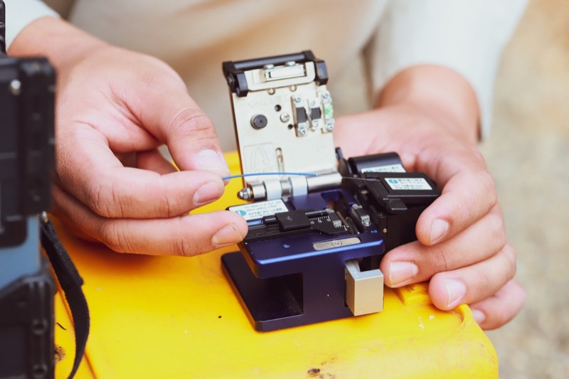
Cleaving Procedure
Open the cleaver. Place the fiber in the fiber holder, with the bare glass extending across the cleave point. The exact cleave length is set by the cleaver fixture -- typical setting is 16mm or 20mm of bare glass beyond the coating. Close the cleaver. The mechanism scores and breaks the fiber automatically. Open the cleaver, retrieve the fiber, and dispose of the cleaved-off scrap into a fiber waste container -- never flick scrap fiber onto the floor or work surface.
Cleaver Maintenance
The cleaver blade is the most consumed part of the splicing kit. Most cleavers allow you to advance the blade to a fresh edge after a number of cleaves (typically every 1,000-3,000 cleaves). When all blade positions are used, the blade must be replaced. A worn blade produces poor cleave angles and chip-out at the end-face, both of which cause splice failures.
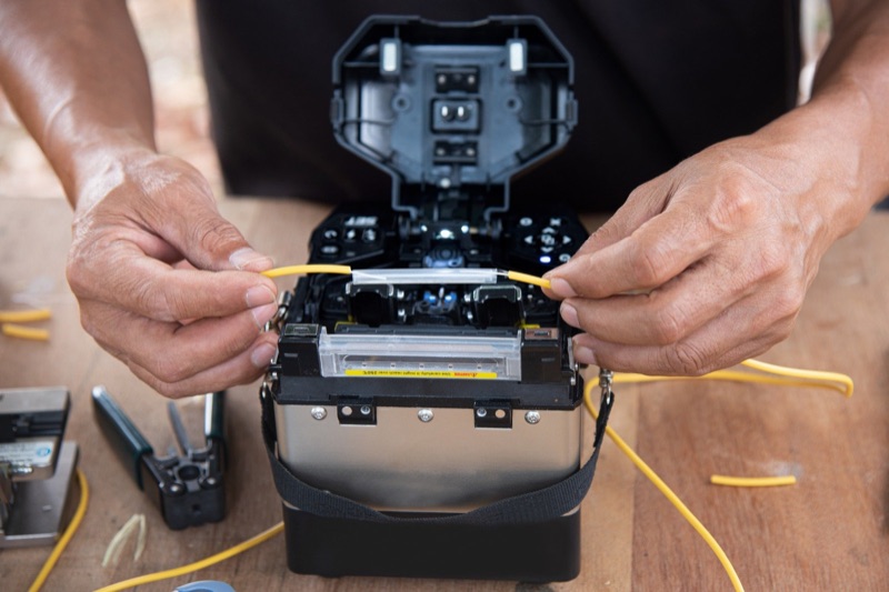
Step 6: Load Fibers and Run the Splice Cycle
Open the windshield cover on the splicer. Place each cleaved fiber in its respective fiber holder, with the bare glass resting in the v-groove and the cleaved end-face just past the electrode position. Close the fiber holders to clamp the fibers. Close the windshield. Press the splice button.
The splicer takes over from here. The cycle proceeds automatically:
- Inspection: Cameras image both fiber end-faces. The splicer checks cleave angles and rejects any fiber with an out-of-spec cleave.
- Pre-fusion: A short low-energy arc cleans residual surface contamination from each end-face.
- Alignment: The splicer moves the fibers in three axes to align the cores (or claddings, on cladding-alignment machines) using image processing.
- Fusion arc: A controlled high-energy arc melts both end-faces and pushes the fibers together. This is the actual splice.
- Loss estimation: The splicer images the completed splice and uses a profile algorithm to estimate the splice loss in dB.
Total cycle time is typically 8-12 seconds. The splicer displays the estimated loss when the cycle finishes. If the estimated loss is above 0.1 dB, re-splice (see fusion splice troubleshooting for diagnosing repeat failures). For a deeper look at how splicers align fibers, see core vs cladding alignment splicers.
Step 7: Apply the Heat-Shrink Sleeve
Open the splicer windshield. Carefully release the fiber holders and lift the spliced fiber pair out of the v-grooves. Slide the heat-shrink sleeve along the fiber until it is centered over the splice point. The sleeve has an internal stainless steel reinforcing rod that should sit alongside the splice for mechanical support.
Place the sleeved splice into the heat oven on the splicer. Close the oven cover. Press the heat button. The oven runs a programmed cycle (typically 30-40 seconds) that shrinks the outer tubing and melts the inner adhesive layer to bond the sleeve to the fiber coating on both sides. When the cycle finishes, the splicer beeps and the sleeve is ready to handle.
Cool Before Handling
The sleeve and the splice are hot immediately after the heat cycle. Let it cool for 30-60 seconds before handling. Bending the sleeve while still soft can cause incomplete bonding or distortion of the glass alignment.
Step 8: Verify Splice Loss
The splicer's estimated loss is just that -- an estimate based on image analysis. The real splice loss is measured with an OTDR shooting from each direction across the splice. The bidirectional average gives the true splice loss; gainers (apparent negative loss) on one direction are normal and indicate fiber mismatch.
For each splice in a closure, plan to verify with an OTDR before sealing the closure. If a splice exceeds the link budget allocation, you can re-splice while the closure is still open, much easier than coming back the next day to crack a sealed closure.
For a complete discussion of acceptance criteria, see fusion splice loss budget explained. For OTDR fundamentals, see OTDR basics.
Quick Reference: Time and Specs
| Step | Time | Spec / Target |
|---|---|---|
| Cable opening | 30-60 sec | 12-18 in. of buffer tube exposed |
| Strip fiber coating | 5-10 sec | 35-40mm bare glass per side |
| Clean bare fiber | 5 sec | 99% IPA, single-direction wipe |
| Slide sleeve on | 2 sec | 40mm or 60mm heat-shrink |
| Cleave | 3-5 sec | Under 1 degree cleave angle |
| Load and splice | 15-20 sec | Estimated loss under 0.1 dB |
| Heat-shrink sleeve | 30-40 sec | Sleeve fully shrunk, no air gaps |
| Cool and tray | 30-60 sec | Sleeve in tray with bend radius management |
| Total per splice | 2-3 min | Experienced tech |
Pro Tips for Consistent Splices
- Replace the cleaver blade on schedule. Track cleave count and replace before quality drops. A new blade prevents cascading splice failures.
- Clean the v-grooves at the start of each session. Debris in the v-grooves causes alignment errors regardless of fiber prep quality. See how to clean fusion splicer v-grooves.
- Inspect electrodes regularly. Worn or contaminated electrodes produce inconsistent arc energy. See fusion splicer electrode replacement.
- Run an arc calibration at the start of each day. Atmospheric pressure and temperature affect arc energy. The splicer's auto-calibration adjusts for current conditions.
- Batch your splices. Strip and cleave both fibers, then load and splice. Switching between prep and splicing breaks rhythm and slows you down.
- Keep the work area clean. Wind blowing dust into an open splicer windshield will cause failures. In aerial closures or windy environments, use a wind shield or work inside a tent.
- Always wear safety glasses. Bare fiber scraps are sharp and the fusion arc is bright. Use laser safety goggles if there is any chance of live fiber.
Frequently Asked Questions
How long does it take to fusion splice a fiber?
The fusion arc itself takes 7-10 seconds. The complete machine cycle including alignment and loss estimation is 8-12 seconds. With prep work (stripping, cleaning, cleaving) and heat-shrink protection, an experienced technician averages 2-3 minutes per splice from start to finish. New technicians should plan on 5-7 minutes per splice until prep work becomes muscle memory.
What splice loss is acceptable in the field?
Industry standard for a passing fusion splice is 0.1 dB or less. Modern core-alignment splicers typically produce 0.02-0.05 dB on single-mode fiber. If the splicer estimates loss above 0.1 dB, re-splice. The estimated loss shown on the splicer is not a real measurement -- final verification is done with an OTDR after the splice closure is sealed.
Can I fusion splice without a cleaver?
No. A precision mechanical cleaver is mandatory. The cleave angle must be under 1 degree for the fusion splicer to align the fibers and produce a low-loss splice. Hand-cleaving with a scribe tool produces angles far too imprecise for fusion splicing -- the splicer will reject the fiber or produce a high-loss splice.
Why does my fusion splicer keep failing on the first attempt?
The most common causes are dirty fiber, bad cleave angles, debris on the v-grooves, and dirty electrodes. Clean the fiber with 99% IPA, advance the cleaver blade or replace it, clean the v-grooves with a cotton swab and IPA, and inspect or replace the electrodes if they are arc-worn.
Do I need to use a heat shrink sleeve on every fusion splice?
Yes. The bare splice point is glass-on-glass with no jacket protection. A heat-shrink splice protection sleeve restores mechanical strength and protects the splice from moisture and physical damage. Skipping the sleeve will result in splice failure within weeks or months as the bare fiber flexes and cracks at the splice point.
Shop Fusion Splicing Tools
Fusion splicers, cleavers, splicing kits, and consumables for FTTH and OSP field work.