Visual Defects on the Splicer Image
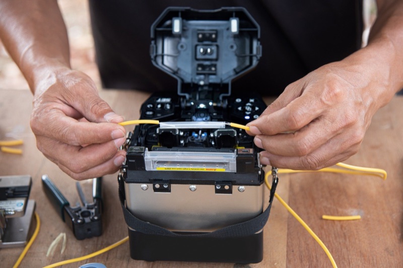
Modern splicers display the splice region on screen after the arc. Visual inspection of the splice image catches problems that the estimated loss alone might miss.
Bubbles
A bubble appears as a dark circular or oval void within the splice region. Bubbles are voids where arc-vaporized contamination expanded and froze into the glass as it solidified. Any visible bubble means high splice loss.
Cause: Contamination on one or both fiber end-faces. Most often skin oil from handling, dust from the work environment, or coating residue not fully stripped.
Fix: Cut back, re-strip, re-clean with 99% IPA, re-cleave, re-splice. If bubbles persist, check the cleaver for contamination -- a dirty cleaver blade transfers debris to the cleaved end-face.
Fat Splice
A fat splice appears thicker in the splice region than the surrounding fiber. The glass has accumulated at the splice point, creating a mound or bulge.
Cause: Too much arc energy, too much fiber overlap during fusion, or both. The fibers were pushed too far together while the glass was molten, displacing material outward.
Fix: Run arc calibration -- the calibration adjusts both arc current and overlap to current conditions. If the problem persists after calibration, check the splice program against the fiber type. The wrong program can deliver wrong arc parameters.
Thin Splice (Necking)
A thin splice (also called necking) appears narrower at the splice region than the surrounding fiber. The fibers were pulled apart slightly during fusion or insufficient material was available to fully bridge the gap.
Cause: Too little arc energy, insufficient fiber overlap, or too long a gap between cleaved end-faces during the alignment phase. Sometimes caused by poor cleave quality where the end-face is not fully perpendicular.
Fix: Re-cleave to ensure perpendicular end-faces, run arc calibration, verify splice program parameters.
Dust Line
A dust line appears as a faint dark line across the splice region, often visible only at higher magnification. Caused by contamination that did not form a full bubble but did create a defect along the splice plane.
Cause: Light contamination on one end-face. Often from inadequate cleaning or from fiber that touched a surface between cleaving and loading into the splicer.
Fix: Re-clean and re-cleave both fibers. Improve cleaning technique -- use fresh sections of wipe, more IPA, more careful handling.
Core Deformation
The core appears bent, displaced, or uneven within the splice region.
Cause: Excessive arc energy melts the glass beyond what is needed for fusion, allowing surface tension and convection currents in the molten glass to deform the core. Also caused by splicing fibers with significantly different mode field diameters.
Fix: Run arc calibration. Verify both fibers are the same type. If splicing dissimilar fibers (legitimately, such as joining different manufacturers), expect some unavoidable loss.
Asymmetric Melt
The splice appears unbalanced -- one side of the splice region looks more melted than the other. The splice region is offset from the center of where the two fibers met.
Cause: Asymmetric arc, usually from worn or contaminated electrodes. One electrode is delivering more arc energy than the other.
Fix: Inspect electrodes. Replace if worn (see fusion splicer electrode replacement). Run arc cleaning cycle if electrodes are mildly contaminated. Always replace electrodes as a matched pair.
Common Splicer Error Messages
"Cleave Angle Too Large"
The splicer measured the cleave angle and rejected the fiber because it exceeds the configured threshold (typically 1.0-3.0 degrees).
Cause: Worn cleaver blade, contaminated cleaver fiber holder, fiber loaded improperly in the cleaver, or twisted fiber during loading.
Fix: Advance the cleaver blade to a fresh position. If all positions are used, replace the blade. Clean the cleaver fixture with IPA. Re-load and re-cleave the fiber, ensuring the fiber sits flat and untwisted in the cleaver fixture. Use a precision Mechanical Cleaver rated for sub-1-degree cleaves.
"Fiber Offset" or "Fiber Misalignment"
The splicer detects that the fiber is not in the expected position in the v-groove.
Cause: V-groove contamination is the most common cause. A piece of fiber scrap or debris is lifting the fiber off the reference surface. Less commonly, the fiber clamp is not seating correctly or the fiber holder is misaligned.
Fix: Clean the v-grooves thoroughly with a cotton swab and 99% IPA. See how to clean fusion splicer v-grooves for the full procedure. Inspect the fiber clamps and clamp seating.
"Arc Calibration Required"
The splicer requests arc calibration, typically because atmospheric conditions have changed or because internal counters have flagged calibration as overdue.
Cause: Normal -- the splicer compensates for atmospheric pressure, temperature, and electrode wear by recalibrating arc current periodically.
Fix: Run the arc calibration routine. Prepare two single-mode fibers and run the routine from the maintenance menu.
"Splicing Failed" or "Re-Splice"
Generic splice failure. Could be any of the visual defects above.
Cause: Multiple possible causes.
Fix: Examine the splice image to identify the defect type, then apply the corresponding fix.
"Cleave Length Error"
The splicer detects that the bare fiber length is outside the expected range -- too short or too long.
Cause: Cleaver fiber holder is set for the wrong cleave length, or the fiber was not loaded to the correct depth in the cleaver.
Fix: Check cleaver fiber holder settings. Verify cleave length matches the splicer's expected setting (typically 16mm or 20mm). Re-cleave with correct positioning.
Quick Symptom-to-Cause Reference
| Symptom | Most Likely Cause | First Action |
|---|---|---|
| High estimated loss (0.1+ dB) | Contamination or bad cleave | Re-clean and re-cleave |
| Visible bubble in splice | End-face contamination | Re-clean and re-cleave |
| Fat splice | Excess arc energy | Run arc calibration |
| Thin splice / necking | Insufficient arc energy or overlap | Run arc calibration |
| Inconsistent results | V-groove contamination or worn electrodes | Clean v-grooves; check electrodes |
| Cleave angle errors repeatedly | Worn cleaver blade | Advance or replace blade |
| Fiber offset errors | V-groove debris | Clean v-grooves |
| Asymmetric melt pattern | Worn / contaminated electrodes | Run cleaning arc; replace if needed |
| OTDR shows splice OK, splicer says fail | False reject (low concern) | Trust OTDR; tighten splicer thresholds if persistent |
| OTDR shows high loss, splicer says good | Mode field mismatch or fiber issue | Verify fiber types match; re-splice |
A Systematic Troubleshooting Approach
When splices start failing in the field, panic is not an option. Work through the diagnostic steps in order. The cheap, fast checks come first.
Step 1: Re-Clean the Fiber
Costs nothing, takes 10 seconds. Wipe the bare fiber with a fresh wipe and 99% IPA, single direction, fresh wipe section. About half of mid-session splice failures are solved by re-cleaning.
Step 2: Inspect the Cleave
Most splicers display the cleave angle measurement. If angles are creeping up (0.5 to 0.8 to 1.0+ degrees), advance the cleaver blade. If you have already used all blade positions, replace the blade.
Step 3: Clean the V-Grooves
Open the splicer, lift the fiber clamps, swab the v-grooves with cotton swabs and 99% IPA. Quick and effective. See how to clean fusion splicer v-grooves.
Step 4: Run Arc Calibration
Calibration adjusts arc parameters for current conditions. Run from the maintenance menu using two prepared single-mode fibers. Calibration consumes a few fibers but is necessary periodically.
Step 5: Check the Splice Program
Modern splicers have multiple splice programs for different fiber types: standard SMF, bend-insensitive G.657, dispersion-shifted, multimode OM3/OM4, etc. Wrong program = wrong arc parameters = bad splices. Verify the program matches the fiber you are splicing.
Step 6: Inspect Electrodes
Open the splicer and examine electrode tips under magnification. Worn or contaminated electrodes need cleaning or replacement. See fusion splicer electrode replacement.
Step 7: Replace Consumables
If splices continue to fail after all the above, you may have multiple consumables at end-of-life. Replace the cleaver blade, replace the electrodes, and run a fresh arc calibration. Sometimes the cumulative effect of mildly worn parts produces splice failures that no single fix resolves.
Step 8: Send for Service
If the splicer continues to fail with fresh consumables and proper procedure, the issue may be internal -- camera misalignment, motorized stage failure, or electrode mount damage. Time to send the splicer in for service. Have a backup splicer or rental ready before this happens in the field.
Environmental Causes of Splice Problems
Wind and Open Air
Splicing in wind brings constant dust into the splicer. Even with the windshield closed, opening it to load fibers exposes the v-grooves and cameras. In an aerial closure or windy outdoor environment, splice failures may be entirely environmental.
Fix: Use a wind shield or work inside a tent. Clean v-grooves more frequently. Keep the windshield closed any time you are not actively loading fibers.
Cold Weather
Cold ambient temperature affects arc energy delivery and battery performance. Below freezing, arc characteristics may drift outside the calibration range.
Fix: Warm the splicer to operating temperature before splicing. Run a fresh arc calibration after the splicer is warm. Use the replacement battery in case cold reduces battery capacity below acceptable levels.
High Humidity
Moisture condensing on the v-grooves, electrodes, or cameras causes contamination and arc instability.
Fix: Allow the splicer to acclimate to environmental conditions before opening. Clean v-grooves and electrodes after exposure to high humidity.
Direct Sunlight
Bright sunlight can wash out the splicer display and interfere with the cameras' ability to image the fibers.
Fix: Shade the splicer with the splicer case lid, a hat, or a tent. Position your body to block direct sun.
When to Trust the Splicer's Loss Estimate
The estimated loss displayed by the splicer is a calculated number based on splice geometry. It is not a real measurement. Sometimes the splicer estimates pass when the splice is actually bad, and sometimes it estimates fail when the splice is actually fine.
When Estimate Is Reliable
For routine splices on standard SMF using core alignment, the splicer estimate is usually within 0.02-0.03 dB of the OTDR measurement. Trust it for go/no-go decisions in the field.
When to Verify with OTDR
Always verify with OTDR before sealing splice closures, especially:
- On the first few splices after replacing electrodes or cleaver blade
- When the splicer estimate is borderline (around 0.08-0.12 dB)
- On any splice involving fibers from different manufacturers
- On any splice where the visual image shows defects
- On long-distance OSP routes where each splice contributes meaningfully to the link budget
The Fiber Ranger OTDR is purpose-built for splice loss verification in the field. For loss budget context, see fusion splice loss budget explained and OTDR basics.
Frequently Asked Questions
Why is my fusion splicer giving me high splice loss?
The most common causes are: dirty fiber, bad cleave angle, debris in the v-grooves, worn or contaminated electrodes, incorrect splice program, or out-of-date arc calibration. Work through these in order: clean the fiber, clean the cleaver, clean the v-grooves, run arc calibration, check the splice program, then check electrodes.
What does a bubble in a fusion splice mean?
A bubble means contamination on the fiber end-face was vaporized by the arc. The vapor expanded into a void that solidified as the glass cooled. Bubbles always cause high splice loss. Re-clean the fiber and cleave a fresh end-face, then re-splice.
Why does my splicer say the cleave angle is too high?
The fusion splicer measures cleave angle and rejects fibers above spec. A high cleave angle usually means the cleaver blade is worn, the cleaver fiber holder is contaminated, or the fiber was loaded incorrectly. Advance the cleaver blade or replace it, clean the cleaver fixtures, and re-cleave.
What is a fat splice and why does it happen?
A fat splice appears thicker than the surrounding fiber. It is caused by too much arc energy or too little fiber overlap during fusion. Run arc calibration, check the splice program parameters, and inspect electrodes for contamination.
Can I fix a bad splice without re-splicing?
No. A bad splice cannot be fixed in place. The only remedy is to cut out the bad splice and make a new splice. Most splicers can re-arc the existing splice, which sometimes recovers a slightly high-loss splice, but it has limited effect. If the estimated loss is above 0.1 dB or there are visible defects, cut and re-splice.
Shop Splicing Tools and Supplies
Replacement cleaver blades, fusion splicer batteries, splicing kits, and OTDRs for verification.