Before You Open the OTDR
The two failures that ruin OTDR results both happen before the first pulse goes down the fiber: dirty connectors and the wrong test parameters. Solve those before you press start and the rest of the workflow is mechanical. Skip them and you will spend the rest of the day chasing artifacts that look like real events but are not.
Read the OTDR basics primer if you need a refresher on how the instrument works. This guide assumes you already understand backscatter, reflective events, and the role of the launch fiber. The focus here is on procedure, not theory.
Confirm the Fiber Is Dark
An OTDR launches optical pulses at hundreds of milliwatts of peak power. If you connect to a live fiber, you will damage the OTDR's receiver and potentially the active equipment on the other end. Before you connect, verify the fiber is dark. If you are not certain, use an Optical Fiber Identifier to detect any traffic on the fiber without breaking the connection.
For FTTH work, this means the OLT port has been administratively disabled and the technician has confirmed no signal at the OLT side. For dark fiber acceptance testing, this is automatic. For carrier maintenance, the fiber must be removed from service and patched out before testing.
Step 1: Inspect and Clean Every Connector
Every connector that mates during the test must be inspected and cleaned. This includes the OTDR's own output port, both ends of the launch fiber, both ends of any receive fiber, and the patch panel ports the fiber under test terminates into.
Inspection
Use a fiber inspection scope on every endface before mating. The WiFi Fiber Microscope shows the endface on a phone or tablet at 200x magnification, which is enough to see contamination, scratches, and pits. Connectors that look clean to the naked eye routinely show contamination under the scope. If the endface shows any contamination in the core or cladding region, clean it.
Cleaning
The fastest method is a one-click cleaner. The CLEP-25 Mini Fiber Cleaner handles 2.5mm ferrules (SC, FC, ST), and the CLEP-125 handles 1.25mm ferrules (LC, MU). One click per connector, then re-inspect. If contamination persists, use a wet-dry technique with isopropyl alcohol and a lint-free wipe. Detailed procedure in our connector cleaning guide.
Step 2: Connect the Launch Fiber
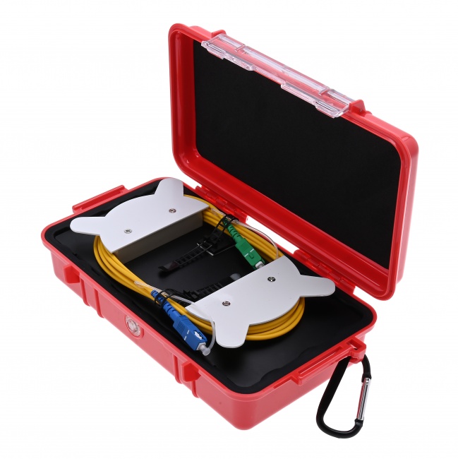
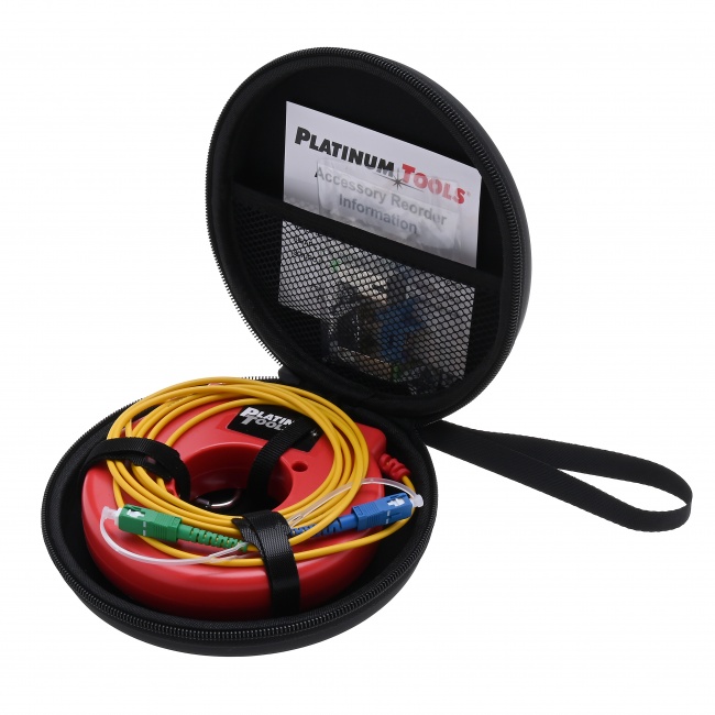
The launch fiber connects between the OTDR's output port and the first connector of the fiber under test. The launch fiber displaces the OTDR's dead zone so the first event of the link is measurable. Without it, the first connector's loss and reflectance are inside the OTDR's blind spot.
Launch Fiber Length
The launch fiber must be longer than the OTDR's longest event dead zone at your test pulse width. A 500-meter launch fiber covers most pulse widths up to 100 ns. For long-pulse testing (1000+ ns) on long-haul links, 1-2 km is appropriate. We cover this in detail in OTDR launch and receive cables.
Connection Order
Connect the launch fiber to the OTDR first, then to the fiber under test. This ensures any contamination disturbed during mating ends up at the OTDR side (where you have already cleaned and verified) rather than at the link side, which is harder to access and may be live in service.
Step 3: Configure Test Parameters
Modern OTDRs have an auto-test mode that picks parameters automatically. For routine FTTH work this is fine. For acceptance testing, troubleshooting, or any documentation work, set parameters manually so you control the resolution, range, and accuracy.
Wavelength
For single-mode fiber, test at both 1310nm and 1550nm. The two wavelengths reveal different problems: macrobends are visible at 1550nm but often invisible at 1310nm; some splice losses are wavelength-dependent. Long-haul testing adds 1625nm for live-fiber monitoring.
For multimode fiber, test at 850nm and 1300nm. The two wavelengths characterize the fiber across both operating windows used by Ethernet and Fibre Channel.
Pulse Width
Pulse width is the single biggest decision in OTDR setup. Short pulses give better resolution between closely spaced events; long pulses give more dynamic range to reach the far end of long links. We cover the trade-offs in detail in OTDR pulse width explained. As a starting point: 5-30 ns for FTTH drops under 5 km, 100-300 ns for metro fiber 5-30 km, 1000-3000 ns for long-haul over 30 km.
Range
Set the distance range to approximately 1.5 to 2 times the expected fiber length. Setting it too short cuts off the trace before the far end. Setting it too long wastes acquisition time and compresses the trace, making events harder to discriminate.
Averaging Time
Longer averaging produces cleaner traces with better event detection. For a quick sanity-check trace, 10-15 seconds is enough. For acceptance documentation, use 60-180 seconds. The time investment is worth it -- noisy traces hide small splice losses and miss low-reflectance events.
Index of Refraction
The OTDR converts pulse round-trip time into distance using the fiber's index of refraction (IOR). Get this wrong by 1% and your distance measurements are off by 1%. Standard single-mode fiber is approximately 1.4677 at 1310nm and 1.4682 at 1550nm. Use the IOR specified by the fiber manufacturer if you have it; otherwise the default is close enough for most purposes.
Step 4: Run the Acquisition
Press start. The OTDR sends thousands of pulses, averages the returned light, and builds the trace. Watch the trace develop -- if it looks obviously wrong (no events, slope much steeper than expected, no end-of-fiber spike), stop and investigate before continuing. Common causes:
- Trace flat with no events: Loose connection somewhere. The OTDR is not coupled into the fiber.
- Steep slope at the start: Dirty OTDR port or launch fiber connector. Inspect and clean.
- No end-of-fiber spike: Range too short, or pulse width too short to reach the end.
- Massive reflection at the start: The launch fiber connector is broken or the OTDR port is damaged.
Step 5: Verify and Save the Trace
When acquisition completes, walk the trace before saving. Verify the launch fiber is visible and looks normal. Verify each event matches what you expect from the network records (number of splices, number of connectors, total length). If something does not match, investigate now -- not after the trace is saved as the official record.
Bidirectional Testing
For accurate splice loss measurements, test from both ends of the link and average the results. Unidirectional traces show "gainers" at splices where the fiber characteristics differ across the splice point. Bidirectional averaging eliminates this artifact and gives the true splice loss. We explain why in OTDR events vs loss.
File Naming
Use a consistent file naming convention that ties each trace to a specific fiber, wavelength, and direction. A typical scheme: SiteA-SiteB_Strand12_1550nm_AtoB.sor. The .sor extension is the standard Bellcore/Telcordia format readable by any OTDR analysis software.
OTDR Test Workflow Summary
| Step | Action | Tool | Time |
|---|---|---|---|
| 1 | Verify fiber is dark | Optical Fiber Identifier | 1 min |
| 2 | Inspect OTDR port and launch fiber | Fiber inspection scope | 2 min |
| 3 | Clean any contaminated endfaces | One-click cleaner | 1 min per connector |
| 4 | Connect launch fiber to OTDR, then to link | Launch fiber spool | 1 min |
| 5 | Configure wavelength, pulse, range, averaging | OTDR menu | 1 min |
| 6 | Run acquisition | OTDR | 30-180 sec |
| 7 | Walk and verify trace | OTDR display | 2 min |
| 8 | Save trace with documented filename | OTDR / SD card | 30 sec |
| 9 | Repeat at second wavelength | OTDR | 3 min |
| 10 | Test from far end (bidirectional) | Walk to other end | 5-30 min |
Recommended OTDR Test Kit
Beyond the OTDR itself, a complete test kit includes inspection, cleaning, and verification tools. The Fiber Ranger OTDR is the entry point for most FTTH technicians. For inspection during the workflow, the WiFi Fiber Microscope with LC-APC inspection tips covers the most common FTTH connectors.
Pair with a Visual Fault Locator to verify fiber continuity before launching the OTDR. The VFL injects red laser light visible at fiber breaks and bends -- a five-second test that catches the obvious problems before you spend ten minutes setting up an OTDR shot.
Wavelength Strategy: Why Both 1310 and 1550 Matter
Single-mode fiber operates across two main windows: the original window around 1310nm and the long-wavelength window around 1550nm. Both should be tested on every link because each reveals problems the other hides.
1310nm Reveals Fiber Quality
At 1310nm, fiber attenuation is around 0.35 dB/km. Splice losses tend to look slightly larger at 1310nm than at 1550nm. Connector losses are similar at both wavelengths. The 1310nm trace is the cleaner reference for diagnosing splice and connector quality without bend-loss interference.
1550nm Reveals Bend Sensitivity
At 1550nm, fiber attenuation is around 0.22 dB/km, and the longer wavelength is much more sensitive to bending. A macrobend that adds 0.1 dB at 1310nm can add 1-3 dB at 1550nm. Comparing the two traces side by side is the easiest way to find bends: events that grow significantly at 1550nm are bend-related.
1625nm for Live Testing
If your network is in service and you need to test fibers carrying GPON or other transmission, 1625nm is required. It falls outside the operational wavelengths of all common transmission systems, so you can run an OTDR shot without disrupting traffic. Most mini OTDRs do not support 1625nm; full-featured OTDRs do. See mini OTDR vs full-featured OTDR for the trade-off.
Bidirectional Testing for Documentation
For acceptance documentation where per-splice loss values matter, test the link from both ends and average the results. Unidirectional measurements are biased by gainer artifacts at fusion splices. Bidirectional averaging eliminates the bias.
How Bidirectional Testing Works
Run the complete OTDR test from end A to end B, save the trace, walk to the other end, run the test again from end B to end A, save that trace too. OTDR analysis software then aligns the two traces and computes the per-event averaged loss.
Time and Logistics
Bidirectional testing doubles the field time per link because you have to physically move to the other end. For long-haul fiber over a kilometer of right-of-way, the second-end test may require driving 30 minutes between sites. Plan for this in your project schedule. A typical bidirectional test of an 80 km backbone link takes about 3 hours including travel.
When You Can Skip It
For routine FTTH drop verification where the only metric is end-to-end loss against a power meter measurement, bidirectional OTDR testing is overkill. Skip it for FTTH and use the power meter for the loss number. For backbone fiber acceptance and any contract requiring per-splice loss documentation, bidirectional is mandatory.
Common Mistakes That Ruin OTDR Tests
- Skipping the launch fiber. Without it the first connector loss is hidden. The first connector is also the most likely to be a problem -- it is the one mating with field equipment.
- Not cleaning the OTDR port. The OTDR port mates with every launch fiber across every job and accumulates contamination quickly. Inspect and clean before every test.
- Wrong pulse width. Too long and you cannot resolve closely spaced events. Too short and you cannot reach the far end. Match pulse width to link length.
- Testing one wavelength. Macrobends are wavelength-dependent. A link clean at 1310nm can fail at 1550nm. Test both.
- Testing one direction. Splice losses measured one direction include gainer artifacts. Bidirectional averaging is the only way to get accurate splice loss.
- Saving the trace before walking it. If the trace is wrong, fix it before the file is the permanent record. Once it is in the test report, errors persist.
How Long an OTDR Test Should Actually Take
Inexperienced techs either rush an OTDR test (and get a useless trace) or spend 20 minutes per fiber (and never finish the day). For most FTTH work, the per-fiber time budget should land between 4 and 6 minutes including all setup, measurement, save, and cleanup steps.
Where the Time Goes
Connector inspect and clean: 60-90 seconds. Pulse width, range, and averaging selection: 30 seconds (most modern OTDRs auto-select reasonably well). The actual trace acquisition: 30-90 seconds depending on averaging time. Save and annotate: 30-60 seconds. The remainder is moving between fibers.
When to Slow Down
Backbone fiber acceptance, bidirectional testing, and any link with multiple splice closures justify slower, more deliberate testing. The cost of redoing a backbone test is far higher than the cost of doing it right the first time. Plan 15-20 minutes per backbone link including bidirectional capture.
Documentation: Make the Trace Useful Tomorrow
An OTDR trace is only as valuable as your ability to find it later. A trace saved with an undescriptive filename in a folder no one can find is no trace at all when a fault appears six months later.
Filename Convention
Use a consistent filename pattern that includes project, link identifier, wavelength, direction, and date. A useful pattern: PROJECT_LINKID_WAVELENGTH_DIRECTION_YYYYMMDD.sor. For example: ACME_FX42_1310_AB_20260424.sor. This is searchable, sortable, and self-describing.
What Goes in the File Notes
Most OTDR formats support free-text notes inside the trace file. Use this field to record the operator, the launch and receive cable serial numbers, the pulse width and range used, and any field observations (weather, splice closure condition, anything that might matter later).
The Acceptance Test Package
For an acceptance test package delivered to a customer, include both the bidirectional OTDR traces (in .sor format and PDF) and the end-to-end power meter measurements. The OTDR proves the link is built correctly. The power meter proves the link delivers the loss budget the customer is paying for.
Build Your OTDR Test Kit
OTDRs, launch fibers, inspection scopes, and cleaning supplies for fiber link characterization. Everything needed to run an OTDR test the right way.