The Two Problems Launch and Receive Cables Solve
Every OTDR has a fundamental limitation: it cannot measure events at the very beginning or end of the fiber it is testing. The reasons are different but the symptoms are the same -- the first and last connector loss values are missing from the trace.
The Dead Zone Problem
The OTDR launches strong optical pulses through its own output port. The reflection from this port saturates the OTDR's receiver for some distance after the launch position. While the receiver is recovering from saturation, it cannot accurately measure events. This recovery distance is called the attenuation dead zone, and it scales with pulse width: a few meters at 5 ns, hundreds of meters at long pulse widths. For background, see OTDR dead zones explained.
Any connector inside this dead zone is not measurable. Without a launch cable, the first connector of the link under test falls inside the dead zone and its loss is invisible.
The End-of-Fiber Problem
The OTDR measures loss by comparing backscatter levels before and after each event. To measure the loss of an event, fiber must exist on both sides of it -- before for the reference level, after for the reduced level after the event. The last connector of a link has fiber before it (the link itself) but no fiber after it. The OTDR cannot calculate its loss.
Without a receive cable, the trace ends at the last connector spike and the OTDR records the reflectance but not the loss.
How Launch and Receive Cables Work
Launch Cable
A launch cable is a coiled fiber 100 meters to several kilometers long, with connectors on each end. One end mates to the OTDR's output port; the other end mates to the first connector of the fiber under test. The launch cable's length pushes the first link connector beyond the OTDR's dead zone, into the region where the OTDR can measure events accurately. The cost is one extra event on the trace (the launch-to-link connector) and the loss of the launch fiber itself, both of which are excluded from the link measurement.
Receive Cable
A receive cable serves the opposite role at the far end. One end mates to the last connector of the link; the other end terminates in either an unmated connector or a non-reflective (gel-blocked) terminator. The receive cable adds backscatter beyond the last link connector so the OTDR can calculate its loss. The receive cable does not need to be as long as the launch cable -- typically 100-200 meters is enough, but matching the launch cable length simplifies kit standardization.
Sizing Launch and Receive Cables
The minimum length is set by the OTDR's attenuation dead zone at your test pulse width. The cable must be longer than the dead zone or the link's first connector still falls in the unusable region.
| Pulse Width | Attenuation Dead Zone | Minimum Cable Length | Recommended Length | Use Case |
|---|---|---|---|---|
| 5-10 ns | ~5 m | 50 m | 100-200 m | FTTH drops, MDU, patch |
| 30 ns | ~15 m | 100 m | 200-300 m | FTTH feeder |
| 100 ns | ~50 m | 200 m | 500 m | Access, short metro |
| 300 ns | ~150 m | 500 m | 500-1000 m | Metro |
| 1000 ns | ~500 m | 1000 m | 1-2 km | Regional, backbone |
| 3000 ns | ~1500 m | 2 km | 2-5 km | Long-haul |
| 10000 ns | ~5000 m | 5 km | 5-10 km | Ultra-long-haul, DWDM |
For most field techs, a 500-meter or 1 km launch cable is the right general-purpose choice. It covers FTTH, access, and metro work without being so long it dominates the trace.
Free: OTDR Launch & Receive Cable Sizing Cheat Sheet
A one-page bench card built from this guide: the pulse-width-to-minimum-length table, APC/UPC and SC/LC connector-matching rules, and the full launch + link + receive test protocol as a printable checklist. Tape it inside your OTDR case lid and never guess a launch length on a job site again. Drop your email and we'll send it over.
No spam. We'll send the resource and the occasional fiber tip. Unsubscribe anytime.
Connector Types and Polarity
Launch and receive cables must match the connector style of the fiber under test. The two big choices: ferrule type (APC vs UPC) and connector form (SC, LC, ST).
APC vs UPC
APC (angled physical contact) ferrules are angled at 8 degrees so any reflected light bounces away from the fiber core rather than back toward the OTDR. APC connectors show much lower reflectance (-60 dB or better) than UPC (-45 to -55 dB). FTTH and modern PON networks use APC throughout. Data center and enterprise networks often use UPC.
Never mate APC to UPC. The ferrule geometry mismatch causes high loss, high reflectance, and possible physical damage to the connector tips. See SC/APC vs UPC connectors for the geometry. Match the launch cable to the link.
Connector Form
SC is the most common FTTH connector. LC is dominant in data center and enterprise. ST is legacy multimode. A complete OTDR kit includes launch cables in the connector forms used in the networks you service. For FTTH, SC/APC and LC/APC cover most cases. For data center, LC/UPC.
The Complete Launch + Link + Receive Protocol
Acceptance testing on a new link with full event documentation uses both cables in series:
- Inspect and clean the OTDR port, both ends of the launch cable, both ends of the receive cable, and both ends of the fiber under test. Use a fiber inspection scope and one-click cleaner.
- Mate the launch cable to the OTDR's output port.
- Mate the launch cable's far end to the first connector of the fiber under test. This connector is now inside the measurable region of the trace.
- Mate the receive cable to the last connector of the fiber under test at the far end. This connector now has fiber after it and its loss can be measured.
- Configure the OTDR with appropriate wavelength, pulse width, range, and averaging for the link length.
- Run the acquisition. The trace will show the launch cable, then the launch-to-link connector, then all link events, then the link-to-receive connector, then the receive cable, then the end of the receive cable.
- Analyze the trace. Mark the launch-to-link and link-to-receive events as the link endpoints. The OTDR can calculate end-to-end link loss between these points and per-event loss for everything in between.
- Test the second wavelength, then walk to the far end and run the test in reverse for bidirectional documentation.
For step-by-step OTDR setup detail, see how to launch an OTDR test step by step.
Caring for Launch and Receive Cables
Launch and receive cables get mated and unmated repeatedly across job sites, and their connectors take a beating. Treat them as test equipment, not patch cords.
- Inspect every endface before every use. A scratched or contaminated launch cable connector affects every trace you take with that cable. Use a fiber inspection scope with the right tip for your connector type.
- Clean before and after each job. A one-click cleaner removes dust and oils. Wet-dry with isopropyl alcohol for stubborn contamination.
- Cap the connectors when not in use. Dust caps prevent contamination during storage and transport.
- Replace if damaged. A scratched connector cannot be polished in the field. Retire the cable rather than continue using it.
- Verify with a reference test. Periodically connect the launch cable directly to the receive cable through a clean adapter and run a trace. The result should be a single low-loss connector event between two long backscatter sections. Anomalies indicate cable damage.
Launch Cable Spool Configurations
Launch cables come in several physical formats, each with trade-offs in convenience, durability, and cost.
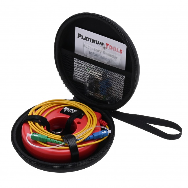
Plastic Reel
The cheapest format. The fiber is wound on a plastic reel with connectors at each end protruding through openings. Inexpensive but fragile -- the reel can crack and the unprotected fiber is easy to damage during transport. Acceptable for occasional use; not recommended for daily field work.
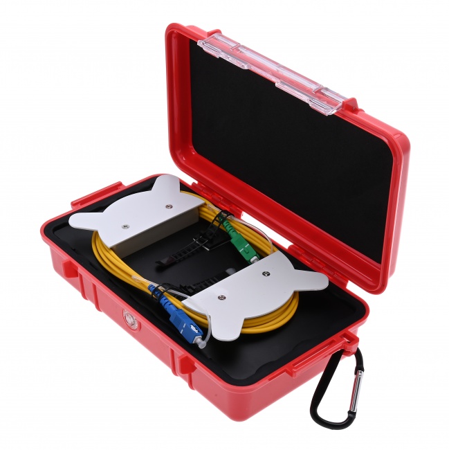
Compact Box
The fiber is wound inside a small plastic or metal enclosure with bulkhead-mounted connectors. Connectors are protected by the enclosure and accessible through panel-mount adapters. Durable enough for daily field use, compact enough to fit in a tool kit. The standard for FTTH crews.
Cassette/Drum Style
For long launch cables (1+ km), a drum-style spool with internal fiber storage and external connector access. Larger and heavier than compact boxes but practical for the longer cables required at long pulse widths.
Pre-Cabled Adapter
Some manufacturers integrate short launch fibers (50-100 meters) into adapter modules that mount directly to the OTDR. Convenient for very short FTTH drops where a 50 m launch is enough, but limited in pulse-width applicability.
Special Cases and Edge Conditions
Multimode Launch Cables
Multimode OTDR testing requires multimode launch fibers matched to the test fiber's core size (50um or 62.5um). Mismatched core sizes cause loss and modal noise that distort the trace. Most multimode test work also requires encircled flux compliance, which means the launch source has a specific modal distribution -- harder to achieve with field-deployable launch cables.
OS2 vs OS1 Single-Mode
Standard single-mode launch cables are interchangeable between OS1 and OS2 fibers. The mode field diameter and core size are similar enough that no special launch fiber is needed for either type.
Bend-Insensitive Fiber
G.657 bend-insensitive fiber has different backscatter characteristics than standard G.652 fiber. Mating G.657 launch to G.652 link or vice versa can produce gainer artifacts at the launch-to-link connector. For acceptance testing on G.657 networks, use G.657 launch fiber. For mixed networks, bidirectional testing eliminates the bias.
Very Short Links
For FTTH drops under 100 meters, the launch fiber can be longer than the link itself. The trace shows a very long launch section followed by a very short link section. This is fine -- the OTDR still characterizes the link normally. But for these short drops, a power meter measurement is often sufficient and faster.
Building Your Launch and Receive Kit
Pair launch and receive cables with the rest of an OTDR test kit:
- Fiber Ranger OTDR -- the OTDR itself.
- WiFi Fiber Microscope with LC/APC inspection tip -- inspect every connector, including launch cable ends.
- CLEP-25 Mini Fiber Cleaner for SC connectors, or CLEP-125 Mini for LC connectors.
- VFL Pen 5km -- a fast pre-test continuity check before you spend time setting up an OTDR shot.
- SC/APC and LC/APC patch cables for connecting to test access ports. The SC/APC simplex jumper and LC/APC duplex jumper handle most needs.
Connector Compatibility: APC vs UPC, SC vs LC
The launch cable's field-side connector must match the link under test. Mating different connector types is either physically impossible or destructive, and mating UPC to APC produces meaningless reflectance numbers even when the connectors share the same form factor.
APC and UPC Are Incompatible
An APC connector has an 8-degree angled end face. A UPC connector has a flat (0-degree) end face. Mating the two creates an air gap on one side of the ferrule and produces 1+ dB of insertion loss plus very high reflectance. APC and UPC bulkheads are typically keyed differently to prevent the mistake, but adapters exist that allow the wrong combination -- avoid them.
Carry Both Variants
Most FTTH networks are SC/APC at the optical line terminal and LC/APC at the optical network terminal, but there is enough variation that a fiber field tech should carry both SC/APC and LC/APC launch cables. Some legacy networks are still UPC, so a UPC launch cable in the kit covers the rest.
Hybrid Patch Cables
For a single launch cable that handles multiple connector types on the field side, hybrid jumpers (e.g., SC/APC to LC/APC) are commercially available. They eliminate the need to swap launch cables when moving between OLT and ONT testing.
Launch Cable Connectors Wear Out
Launch cables get connected and disconnected dozens of times per day. The connectors at both ends -- the OTDR-side connector that mates with the OTDR port and the field-side connector that mates with the link under test -- accumulate wear faster than any other fiber connectors in your kit.
Inspect After Every 10-20 Mates
The end face accumulates particles from every mating cycle. After 10-20 mates without cleaning, contamination is significant enough to affect measurements. After 100 mates without cleaning, contamination is severe enough to permanently scratch the ferrule. Inspect, clean, re-inspect.
Replace Worn Connectors
End faces eventually accumulate scratches that cleaning cannot remove. When a connector inspection shows a Zone B (cladding) scratch that crosses the core, the connector is at end of life. For a launch cable used daily, expect to retire connectors every 6-12 months.
Reflectance Drift Over Time
A new APC launch cable has reflectance better than -65 dB at the OTDR mating connector. After heavy use, reflectance can degrade to -55 dB or worse. The trace will show a larger initial spike, and the OTDR's first-event characterization may suffer. If reflectance is climbing, replace the cable.
Cleaning the Launch Cable Connectors
Both ends of the launch cable need cleaning before every use. The OTDR-side connector picks up debris from the OTDR bulkhead. The field-side connector picks up debris from whatever was just disconnected from it.
Mechanical Click-Cleaners First
A mechanical click-cleaner like the CLEP-25 handles 90% of contamination in one stroke. Clean both ends of the launch cable, then inspect with a fiber inspection scope. If the inspection passes IEC 61300-3-35 zone criteria, mate.
Wet Cleaning for Stubborn Contamination
If a click-cleaner does not remove a smear or fingerprint, escalate to wet cleaning with optical-grade isopropyl alcohol on a lint-free wipe. Pull the connector across the wipe in one direction, then re-inspect. Repeated wet cleaning can leave residue, so end with a dry click-cleaner pass to remove any leftover alcohol.
Inspect Every Time
The temptation to skip inspection is the most common cause of bad OTDR traces. A 30-second inspection cycle catches contamination that would otherwise add 0.5-2 dB of false loss to the first event. The inspection scope pays for itself the first time it saves a re-roll to the customer site.
Storage and Handling
Launch and receive cables are precision instruments, not patch cables. Treat them accordingly.
Use the Original Box or a Padded Case
Spool launch cables stored loose in a vehicle truck bed will have damaged connectors and pinched bend points. Either keep the cable in its original protective case, or upgrade to a hard-shell test equipment case.
Cap Connectors When Not in Use
Dust caps protect end faces from airborne particles between uses. A connector that sits uncapped overnight in a humid van will need full inspection and cleaning before use. Capped connectors stay clean for weeks.
Avoid Sharp Bends in Storage
Bend-insensitive fiber tolerates tighter radii than older fiber, but every cable has a minimum bend radius. Coil with at least 4 inches of radius. Pinching a launch cable in a tool drawer for months can introduce permanent macrobends and a non-flat backscatter section that contaminates every test.
Not sure which launch and receive cables your OTDR and network actually need?
Tell us your OTDR model, the pulse widths you run, and whether your links are SC/APC, LC/APC, or UPC — a fiber specialist will spec the exact launch cable length, connector type, and spool format (ring, box, or drum) for your work, and tell you where a shorter, cheaper cable is fine. No upsell, just the right kit for how you test.
“We were guessing on launch lengths and losing the first connector on half our acceptance traces. They specced a 1 km box for our OTDR and an APC ring for FTTH — every event documents cleanly now.” — FTTH construction QC lead
OTDR Test Kit Equipment
Single-mode launch cables in ring and box formats, the Fiber Ranger Mini OTDR, inspection scopes, and cleaners — everything you need to characterize a fiber link with proper launch and receive cable setup.