The Quick Answer
What an MPO Trunk Actually Is
An MPO trunk is a small-diameter optical cable factory-terminated with multi-fiber MPO connectors on each end. A 12-fiber trunk holds 12 individual 250 micron fibers in a ribbon or loose-tube structure inside a single jacket roughly the diameter of a thick pencil. The MPO connector consolidates all 12 fibers into a single ferrule that mates in one motion -- replacing 12 individual LC duplex jumpers with a single cable, single connection, and single endface inspection.
The density advantage is real. A 144-fiber MPO trunk (twelve 12-fiber MPOs in one jacket) takes the place of 72 LC duplex jumpers. The pulling labor, pathway congestion, and cable management complexity all drop dramatically.
MPO vs MTP: What's the Difference?
MPO is the generic connector standard defined by IEC 61754-7. MTP is a registered trademark of US Conec for an enhanced MPO connector with several engineering improvements. The differences are subtle but meaningful for high-fiber-count work.
- Removable housing. MTP allows field re-gendering by swapping the housing without re-terminating fibers.
- Improved spring design. MTP uses a centered spring that applies more uniform pressure across all fibers.
- Elliptical boot strain relief. Reduces fiber stress at the cable exit.
- Tighter ferrule tolerances. Better optical performance, especially on insertion loss and reflectance.
MTP and MPO are mechanically intermateable -- you can plug an MTP into an MPO adapter and vice versa. For premium data center work, MTP-branded trunks are the de facto standard. For more on the connector itself, see our MPO/MTP fiber connector guide.
Choosing the Fiber Count
| Trunk Size | Connector Type | Typical Use | Fan-Out at Cassette |
|---|---|---|---|
| 8-fiber MPO | MPO-8 | 40G/100G parallel optics direct | 4 LC duplex (rare) |
| 12-fiber MPO | MPO-12 | General 10G/40G/100G, most common | 6 LC duplex |
| 24-fiber MPO | MPO-24 | High-density 100G/400G, parallel optics | 12 LC duplex |
| 72-fiber trunk (6x MPO-12) | 6 MPO connectors | Backbone between MDA and HDAs | 36 LC duplex per panel |
| 144-fiber trunk (12x MPO-12) | 12 MPO connectors | High-density backbone, hyperscale | 72 LC duplex per panel |
For most enterprise builds, 12-fiber MPO is the right default. A 24-fiber MPO doubles the fan-out density and natively supports parallel optics that need more than 8 fibers. For backbone runs between distribution areas, multi-MPO trunks (72 or 144 fibers) reduce pull labor.
Polarity: A, B, or C
Polarity in an MPO system means the mapping of fiber positions from one end of the trunk to the other. Three methods exist:
- Method A (straight-through). Fiber position 1 maps to position 1, 2 to 2, and so on. Requires a polarity flip somewhere in the channel (typically in one of the patch cords) to swap transmit and receive.
- Method B (reverse pair). Fiber position 1 maps to position 12, 2 to 11, and so on. The trunk itself flips, and standard duplex patch cords work at both ends.
- Method C (pair-swapped). Adjacent fiber pairs are swapped (1-2 becomes 2-1) but the overall ordering is straight. Used in legacy systems.
Method B is the most common in modern data center design because it eliminates the need for a special crossover patch cord and works with standard duplex jumpers at every cabinet. Method A is common in environments that already standardized on it. Method C is rare in greenfield builds. Whatever method you pick, use it everywhere -- mixed polarity in the same cable plant is a major source of intermittent failures. See our MPO polarity methods A, B, and C explained for the diagrams.
Key Orientation and Gender
Key Up vs Key Down
The MPO connector has a small key on the housing that orients it in the adapter. Key-up means the key is on the top of the connector when plugged in; key-down means the key is on the bottom. The combination of key orientations at each end of the trunk and the polarity method (A/B/C) determines whether the system maps fibers correctly.
Gender (Pinned vs Unpinned)
MPO ferrules align using two precision pins. A pinned (male) connector has two protruding pins; an unpinned (female) connector has the receptacles. Every mating requires one of each. The standard data center practice is unpinned trunks with pinned cassettes -- trunks ship unpinned, cassettes have pins, and the trunk-to-cassette mating produces a correctly pinned interface.
The downstream side of the cassette (the LC duplex side) goes to LC duplex patch cords like the SM LC/UPC Duplex Patch Cord for single-mode or the MM OM4 Simplex Jumper for multimode (in pairs).
Specifying a Trunk Order
A complete MPO trunk specification includes the following fields. Missing any one of them will get you a trunk that does not work in your system.
- Fiber count. 8, 12, 24, or higher (for multi-MPO trunks).
- Fiber type. OM3, OM4, OM5, or OS2.
- Connector type. MPO or MTP-branded.
- Polarity method. A, B, or C.
- Key orientation, end A. Key-up or key-down.
- Key orientation, end B. Key-up or key-down.
- Gender, end A. Pinned (male) or unpinned (female).
- Gender, end B. Pinned (male) or unpinned (female).
- Length. In meters, plus a small allowance for service loops.
- Jacket type. Plenum (OFNP), riser (OFNR), or low-smoke zero-halogen.
Most vendors require all of the above on a quote. If your supplier asks for fewer fields, push back -- a missing spec results in a trunk you cannot use.
Testing MPO Trunks
Test every MPO trunk on arrival, before installation. A failed trunk is far easier to RMA before it has been pulled through 200 feet of overhead pathway and dressed into panels.
Endface Inspection
Inspect both endfaces of every fiber on every connector. MPO endfaces accumulate contamination quickly and a single contaminated fiber can fail the trunk for production use. Use a video probe with an MPO inspection tip or, for cleanliness only, the WiFi Fiber Microscope with appropriate tips.
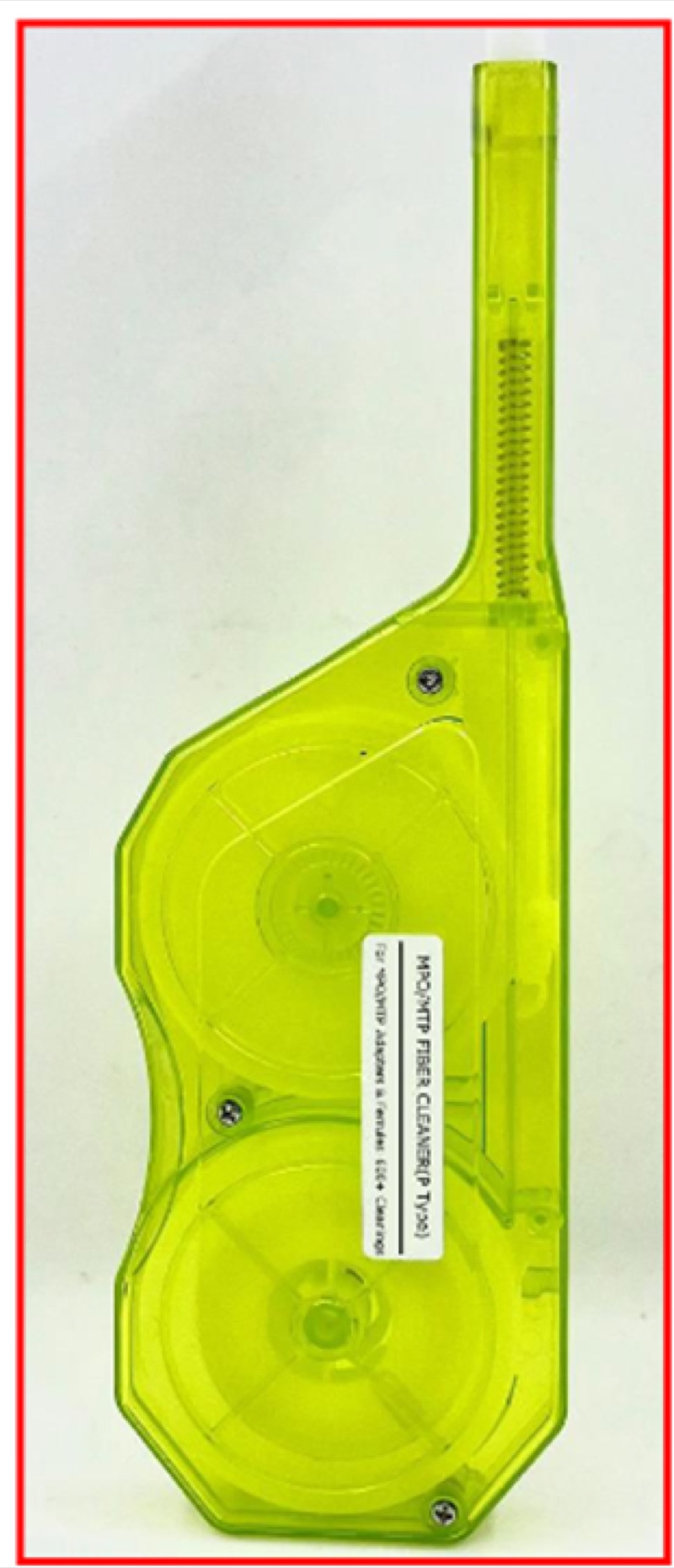
Cleaning
Clean every endface before mating. The MPO Push-Type Cleaner handles standard MPO. For ribbon-style MPO terminations, the MPO R-Type Cleaner matches the form factor.
Insertion Loss
Measure end-to-end insertion loss with an OLTS that supports MPO. Per TIA-568, the maximum insertion loss for an MPO connector pair is 0.75 dB. Trunks should measure significantly better -- typical factory-terminated MPO connectors achieve 0.20 to 0.35 dB.
OTDR Trace
For trunks longer than 50 m or any application requiring Tier 2 certification, run an OTDR trace through a fan-out cable from the MPO to a single fiber input on the OTDR. The Fiber Ranger OTDR handles typical data center trunk lengths.
Real-World Install Scenarios
Three field scenarios that illustrate why the trunk-and-cassette model wins for the long haul.
Scenario 1: 100G spine-leaf rollout in an existing OM4 plant
An operator with a mature OM4 trunk plant adds a new 100G spine layer. The plant was originally built with MPO-12 Method B trunks for 40G-SR4. For 100G-SR4, the same trunks land on new MPO-12 to 4xLC breakout cassettes; for 100G-SR1.2 (single-pair) the same trunks feed LC duplex cassettes. The trunks do not move. Only the cassettes change. A 96-cabinet rollout completes in two weekends without pulling a single new fiber.
Scenario 2: Cross-vendor MPO mismatch caught at acceptance
A general contractor mixes MPO-24 trunks from vendor A (female-female, pinned at one end) with cassettes from vendor B (expecting male-male trunks). Visual inspection during acceptance catches the mismatch in 30 minutes. Without endface inspection and gender verification on arrival, the mismatch would have been discovered at cutover at 2 a.m. with downtime cost in the tens of thousands. The lesson: gender, key orientation, and pin/no-pin status are checked on every trunk before it leaves the staging cart.
Scenario 3: 400G-DR4 cutover requiring single-mode trunks
A hyperscale tenant moves from 100G-SR to 400G-DR4 optics, which require single-mode rather than multimode. The original MPO-12 OM4 trunks are now scrap for the upgraded racks. Provisioning had anticipated this: each cabinet had been pulled with both an OM4 MPO-12 and an OS2 MPO-12 from day one. Cutover involves swapping the cassette type and the patch cords; the SM trunk that was sitting dormant for three years comes online. Dual-fiber-type provisioning at build doubled the trunk cost on day one and saved seven figures of pull-labor on the upgrade.
Scenario 4: MPO-24 to dual MPO-12 breakout for parallel optics migration
A regional cloud provider runs an existing MPO-24 plant for 100G-SR4 with breakout cassettes. A subset of racks migrates to 200G-SR4 (which uses the same physical 12-fiber arrangement but at higher per-lane speeds) and another subset migrates to 400G-SR8 (which needs all 16 fibers active in an MPO-16 footprint). The MPO-24 trunks in the first group continue to work without modification. The second group requires new MPO-16 trunks pulled to those specific racks. Because the original trunks were documented with both physical pinout and intended polarity diagram, the planning team identified the rack-by-rack scope in a single afternoon rather than crawling under raised floor for a week.
Trunk Procurement Checklist for Operations
A practical checklist to attach to every MPO trunk RFQ before sending it to a supplier. Missing any one of these typically results in a trunk that has to be returned or worked around in the field.
- Fiber type and category. OM3, OM4, OM5, OS2 G.652.D, OS2 G.657.A1 — each one is a different SKU.
- Fiber count and connector count. 12, 24, 32, or higher; ribbon vs single-jacket; pinned vs unpinned at each end.
- Polarity method. Method A, B, or C must be specified per the cassette plan, not as a default.
- Key-up / key-down orientation at each end. Document with a sketch, not just a description.
- Length tolerance. Specify both nominal length and acceptable tolerance band; pre-terminated trunks are cut to length and cannot be field-trimmed without re-termination.
- Jacket rating. OFNR, OFNP, or LSZH per the pathway code requirement.
- Color. Aqua for OM3, magenta or violet for OM4, lime for OM5, yellow for OS2 — visual confirmation prevents mid-install confusion.
- Mechanical pull strength. Required for any trunk that will be pulled through long pathways or subduct.
- Test data delivery format. Per-fiber insertion loss results in CSV or PDF; reject trunks that ship without per-fiber test data.
MPO Trunk Lifecycle and Replacement Planning
MPO trunks are a long-lived asset, but they do age. The connectors wear; the fibers can suffer microbend damage from years of moves and adds; jacket integrity in a poorly conditioned space can degrade. Treat every trunk as a finite-life asset with a replacement plan.
- Mating cycle limit. Standard MPO connectors are rated for 200 to 500 mating cycles before insertion loss exceeds the original spec. Cassettes that see frequent moves can hit this limit in five years.
- Quarterly endface inspection on highly-mated trunks. Spine-leaf trunks see far more mating cycles than tenant cross-connects. Inspect quarterly; tenant trunks can be on a longer cycle.
- Document the original test data. Without the original per-fiber IL baseline, drift detection is impossible. Store baseline data with the cable plant documentation, not with one technician's email.
- Plan for trunk replacement at five-year intervals on high-utilization paths. The cost of pre-emptive replacement during a planned window is far lower than the cost of an unplanned outage caused by a degraded connector.
MPO Trunk Acceptance Testing Workflow
A repeatable acceptance testing workflow saves enormous trouble downstream. The following workflow handles a typical batch of pre-terminated MPO trunks arriving at a build site.
- Visual inventory check. Confirm count, length, and SKU against the purchase order before opening any sealed packaging.
- Endface inspection per fiber per connector. Use a video probe with the appropriate MPO inspection tip. Record pass/fail per fiber per connector.
- Cleaning if any fiber fails inspection. Clean and re-inspect; replace the cassette if cleaning does not resolve.
- Bidirectional insertion loss measurement. An OLTS test from end A to end B and from end B to end A; record per-fiber IL in both directions.
- Pass/fail comparison to factory test data. Field IL should be within 0.1 dB of the factory baseline; any fiber outside that band warrants a return to the supplier.
- Acceptance documentation. Test results, photos of acceptance test setup, and signed acceptance sheet stored in the project documentation set.
This workflow takes about 15 minutes per trunk for a 12-fiber MPO trunk and roughly 30 minutes for a 24-fiber. The investment prevents trunks with hidden defects from being installed and discovered at cutover.
Common Questions From Cabling Engineers
What is the difference between MPO and MTP?
MPO is the generic IEC standard for the multi-fiber push-on connector. MTP is US Conec's branded implementation of the MPO standard with refined mechanical tolerances. The two intermate without issues, and most operators specify "MPO" in RFQs while accepting MTP-branded product.
Should we standardize on MPO-12 or MPO-24?
Most current and near-term applications fit MPO-12 (12 fibers in a single connector). MPO-24 doubles density but is harder to clean and inspect. For greenfield builds with anticipated 400G adoption, MPO-12 with parallel optics remains the safest default; MPO-24 is appropriate where cabinet density and the upgrade path both demand it.
Can MPO trunks be field-trimmed if too long?
Pre-terminated MPO trunks cannot be field-trimmed without re-terminating the affected connector, which generally requires sending the trunk back to the manufacturer. Always confirm length before installation; "close enough" length tolerances cause expensive returns.
How do I confirm polarity on a delivered trunk before install?
Light a known fiber position on one end with a visual fault locator and confirm which fiber position lights up on the other end. Repeat for at least two fiber positions to confirm the polarity method matches the documentation. This 5-minute check on arrival prevents hour-long polarity troubleshooting at cutover.
What jacket rating do MPO trunks need in plenum spaces?
OFNP (optical fiber non-conductive plenum) is required for any MPO trunk run in plenum return air spaces. OFNR is acceptable for riser pathways only. The jacket rating must be specified in the RFQ; default supplier stock varies and may not match the install location code requirement.
Do we need a separate cleaner for MPO and LC connectors?
Yes. MPO and LC use different ferrule geometries; a cleaner designed for one will not properly clean the other. Stock dedicated MPO cleaners and dedicated LC cleaners on every install cart, and label them so technicians do not cross them.
How do we handle a trunk that arrives with a failed inspection?
Document the failure with photos of the problem connector, contact the supplier with the inspection records, and request an RMA. Do not install a trunk with a known inspection failure; the failure will resurface during acceptance testing or operations and the cost of replacement after install is many multiples of the cost of an RMA before install.
What is the realistic per-fiber insertion loss for a quality MPO trunk?
Factory-terminated MPO connectors typically achieve 0.20 to 0.35 dB per connector pair. The TIA-568 maximum is 0.75 dB. Trunks measuring above 0.5 dB on any fiber pair warrant a closer look at endface condition before being released to production.
How long can MPO trunks be stored before installation?
In their original sealed packaging with dust caps in place, MPO trunks store essentially indefinitely. Once unpacked, every connector should be cleaned and inspected before mating regardless of how recently it was unpacked. Treat unpacking as the start of the contamination clock.
Should we specify pinned or unpinned connectors for our trunks?
The general convention is pinned at one end and unpinned at the other end of any trunk, with the cassette on the pinned end. Specifying both ends pinned or both ends unpinned almost always indicates a planning error. Document the pin convention on the cabinet schematic so future technicians know which end is which without having to inspect connectors physically.
The Bottom Line
MPO trunk cable is the workhorse of modern data center fiber. Specifying it correctly takes a dozen fields but those fields do not have defaults you can guess. Polarity, key orientation, gender, and fiber type are not interchangeable -- each must match the cassettes and patch cords you intend to use. Test every trunk on arrival, clean every endface before mating, and document polarity and key orientation at every patch panel.
For broader context, see our structured fiber cabling for data centers guide and the fiber cassette vs direct trunk comparison. For the polarity diagrams in detail, see MPO polarity methods A, B, and C explained.