What MPO and MTP Are
MPO stands for Multi-fiber Push-On. It is a connector form factor that holds multiple fibers in a single rectangular ferrule, with the fibers arranged in one or more rows. The original MPO connector had 12 fibers in a single row. Variants now include 8-fiber, 16-fiber, 24-fiber (two rows of 12), 32-fiber, and 72-fiber designs. The mechanical housing uses a push-pull engagement similar to SC, but the alignment is achieved by precision metal pins rather than a single ferrule.
MTP is a registered trademark of US Conec for their MPO-compatible connector line. MTP connectors meet or exceed MPO standards and are mechanically interchangeable with MPO from any manufacturer. The MTP design includes specific enhancements: a removable housing for re-polishing, oval guide pins for tighter alignment tolerance, a floating ferrule for better contact under cable strain, and elliptical guide holes. In casual usage, "MPO" and "MTP" are often used interchangeably, but technically MTP is a brand of MPO.
Where MPO Is Used
MPO connectors are the standard interface for parallel optics in data centers. Parallel optics multiplex Ethernet traffic across multiple fiber pairs simultaneously rather than packing more bandwidth onto a single wavelength. Major applications:
- 40GBASE-SR4: 40Gb Ethernet over multimode using 4 transmit and 4 receive fibers, each running 10Gb. Uses 8 of 12 fibers in a 12-fiber MPO.
- 100GBASE-SR4: 100Gb Ethernet over multimode using 4 transmit and 4 receive fibers, each running 25Gb. Same 8-fiber footprint.
- 100GBASE-SR10: Earlier 100GbE multimode standard using 10 fibers each direction (20 total) over 24-fiber MPO. Largely superseded by SR4.
- 400GBASE-SR4.2 and SR8: 400Gb Ethernet using 8 or 16 fibers depending on the variant.
- 800GBASE-SR8: 800Gb Ethernet using 16 fibers (8 lanes each direction at 100Gb per lane).
- Structured cabling trunks: Long pre-terminated MPO trunks connect cabinets and aggregation rows, distributing fiber via MPO-to-LC breakout modules.
MPO is also used in some PON distribution architectures and in central office cross-connects where high fiber density is required.
Pinning: The Most Critical MPO Detail
An MPO ferrule has two precision-machined holes on either side of the fiber array. Alignment between two mated MPO connectors is achieved by metal pins that protrude from one ferrule and seat into the holes of the other. Without correctly matched pinning, the two ferrules cannot align, and the fibers will not couple optically.
Pinned (Male) and Unpinned (Female)
- Pinned MPO (male): Has two metal pins protruding from the ferrule.
- Unpinned MPO (female): Has empty alignment holes ready to receive pins.
For two MPO connectors to mate, one must be pinned and one must be unpinned. Pinned-to-pinned attempts crush the pins. Unpinned-to-unpinned attempts have no alignment and cause severe insertion loss.
Common Pinning Conventions
The widely-adopted pinning convention for structured cabling:
- MPO trunks (long pre-terminated cables between modules): Pinned (male) on both ends.
- MPO modules (cassettes that break MPO out to LC): Unpinned (female) on the MPO side.
- MPO patch cords (short cables for transceiver-to-module): Unpinned on both ends, since they connect a pinned trunk on one side and a pinned transceiver on the other -- wait, this depends.
- MPO transceivers (40G/100G/400G optics): Typically pinned (male) at the transceiver port.
The result of these conventions: in a typical link, you have a pinned transceiver -> unpinned patch cord -> pinned trunk -> unpinned module -> LC breakouts. Every mating pair has one pinned side and one unpinned side. Plan your inventory accordingly.
Polarity: Methods A, B, and C
Polarity is how the fibers in an MPO array map from one end of a link to the other. Maintaining correct polarity ensures that transmit on one side connects to receive on the other. TIA-568 defines three polarity methods.
Method A (Straight-Through)
Each fiber position maps to the same position at the other end. Position 1 to position 1, position 2 to position 2, and so on. This requires different patch cords at the two ends of the link to achieve duplex polarity (an A-to-B patch cord on one side, A-to-A on the other), which complicates field operations.
Method B (Reversed)
The fiber positions are mirrored end-to-end. Position 1 maps to position 12, position 2 to position 11, and so on. This produces correct duplex polarity with identical patch cords at both ends -- a major operational advantage. Method B has become the dominant choice for new data center deployments.
Method C (Pair-Wise Crossover)
Fibers are crossed in pairs. Position 1 maps to position 2, position 3 to position 4, and so on. Requires similar mixed patch cords as Method A in some configurations. Less common in modern installations.
The polarity method must be consistent across an entire structured cabling system. Mixing Method A and Method B components in the same link will result in transmit-to-transmit and receive-to-receive connections, which will not work. Document your polarity choice and stock matching components.
Free: MPO/MTP Ordering & Field Checklist
A one-page printable card for the rack: pinning (male/female by component), the three polarity methods side-by-side, fiber-count picks by Ethernet speed, UPC-vs-APC polish, and the cleaning/inspection steps before you mate. Sized to laminate and zip-tie to the patch panel so nobody orders the wrong trunk again. Drop your email and we'll send it over.
No spam. We'll send the resource and the occasional fiber tip. Unsubscribe anytime.
Fiber Counts: 8, 12, 16, 24
| Fiber Count | Configuration | Primary Use |
|---|---|---|
| 8-fiber | One row of 8 | 40/100GBASE-SR4 native, no unused fibers |
| 12-fiber | One row of 12 | Most common; supports SR4 (8 used, 4 unused) and structured cabling |
| 16-fiber | One row of 16 | 400GBASE-SR8, 800GBASE-SR8 native |
| 24-fiber | Two rows of 12 | High-density trunks, legacy 100GBASE-SR10 |
| 32-fiber | Two rows of 16 | 800GbE and emerging higher speeds |
The choice between 8-fiber and 12-fiber for 40/100GbE installations is a perennial debate. 8-fiber MPO uses every fiber for traffic, eliminating the four "wasted" fibers in a 12-fiber connector but requiring more frequent connector terminations as you scale. 12-fiber MPO is more flexible because it can serve both SR4 (8 fibers) and other applications, and it is the historical default for which the most products are available.
Polish: MPO/UPC and MPO/APC
Like single-fiber connectors, MPO ferrules are polished to either UPC (flat) or APC (8-degree angled) specifications. The polish determines back-reflection performance.
- MPO/UPC: The data center standard. Used for 40/100/400/800GBASE-SR parallel optics. Return loss greater than -25 dB per fiber typical (parallel optics is less sensitive to back-reflection than single-fiber single-mode).
- MPO/APC: Used in some PON distribution applications, single-mode trunks where back-reflection control is important, and any MPO link carrying signals sensitive to reflection. Return loss greater than -55 dB per fiber typical.
For more on polish geometry, see our guides to SC/APC vs UPC connectors and APC vs UPC explained.
Cleaning and Inspecting MPO Connectors
MPO ferrules are notoriously difficult to clean. The rectangular ferrule has no rotational symmetry, the fibers are spaced close together, and contamination on any one fiber position degrades that channel's performance. A single dirty fiber in a 12-fiber MPO array can take down a 100GBASE-SR4 link.
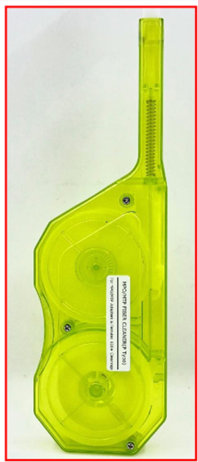
Cleaning Tools
Use cleaners specifically designed for MPO ferrules. Push-type and reel-type MPO cleaners advance a microfiber wipe across the entire ferrule face in a controlled motion, cleaning all fibers simultaneously without leaving residue. Standard one-click cleaners designed for LC or SC will not work on MPO -- the ferrule shape and fiber array width are different. Browse our push-type MPO cleaner and reel-type MPO cleaner.
Inspection
MPO inspection requires scopes with MPO-compatible probe tips that can image multiple fiber positions in sequence. Standard single-fiber inspection tips will not fit an MPO ferrule. The inspection must verify cleanliness on every fiber position. For multi-fiber inspection, see our WiFi fiber microscope with appropriate MPO tip accessories.
For routine cleaning practices, see our fiber cleaner guide.
Testing MPO Links
Testing MPO links is more involved than single-fiber testing because each fiber position must be verified individually. Three approaches:
- MPO test fanout: A short test cord with MPO on one end and 12 individual LC connectors on the other lets you measure each fiber's loss with a standard LC-port power meter or OTDR. Rotate through each LC position to test each fiber.
- MPO-native test equipment: Specialized MPO testers integrate the fanout internally and produce per-fiber pass/fail results in a single pass. Faster but more expensive.
- OTDR with MPO breakout: An OTDR with an MPO test cord identifies the location of any high-loss event in a multi-fiber link.
Test polarity, pinning, and per-fiber loss for every MPO link before it goes into service. The cost of finding a polarity error before bringing up production traffic is far lower than after.
Common MPO Installation Pitfalls
- Wrong pinning at the wrong end: Ordering pinned trunks for an unpinned-on-both-ends application, or vice versa.
- Polarity mismatch: Mixing Method A modules with Method B trunks. The link will not pass duplex traffic.
- Contaminated ferrules: MPO connectors that have been cycled multiple times without cleaning will have intermittent or high-loss links.
- Fiber count mismatch: Connecting an 8-fiber MPO to a 12-fiber adapter (or vice versa) -- the connectors are the same outer dimensions but the fibers will not align.
- Polish mismatch: Mating MPO/UPC to MPO/APC. Same problem as single-fiber UPC-to-APC -- high loss, high reflection, ferrule damage.
Frequently Asked Questions
What is the difference between MPO and MTP?
MPO is the generic IEC and TIA standard for multi-fiber array connectors. MTP is US Conec's proprietary, performance-enhanced implementation of the MPO standard. MTP connectors are mechanically intermateable with MPO and meet all MPO specifications, but include design refinements such as a removable housing, oval guide pins, floating ferrule, and tighter tolerances. All MTP connectors are MPO; not all MPO connectors are MTP.
What does pinned vs unpinned mean for MPO?
An MPO connector with two metal alignment pins protruding from the ferrule is pinned (male). A connector without pins is unpinned (female). For MPO connectors to mate, one side must be pinned and the other unpinned. The pins ensure precise alignment of the fibers in the array. Patch cords are typically unpinned-to-unpinned, while module trunks are pinned-to-pinned, requiring careful planning.
What are MPO polarity types A, B, and C?
TIA-568 defines three MPO polarity methods. Type A uses straight-through wiring, requiring different patch cords at each end to maintain duplex polarity. Type B uses reversed wiring, producing duplex polarity with identical patch cords at both ends. Type C uses pair-wise crossover. Type B is the most common for new data center deployments because it simplifies field operations.
Can I clean an MPO connector with a standard fiber cleaner?
No. Standard one-click cleaners are designed for round single-fiber ferrules (LC, SC, FC). MPO ferrules are rectangular with multiple fibers, and the cleaning surface and motion are different. Use MPO-specific push-type or reel-type cleaners that match the ferrule geometry. Using a standard cleaner on an MPO connector will not effectively clean all fiber positions and may push contamination across the array.
Related Reading
- Fiber Endface Cleaning Guide -- detailed cleaning techniques including MPO.
- APC vs UPC Explained -- polish geometry that applies to MPO and single-fiber connectors.
- Single-Mode vs Multimode Fiber -- the fiber type drives many MPO design decisions.
Speccing an MPO/MTP link and not sure what to order?
Tell us what you're building — transceivers, trunk lengths, cassettes or direct-attach, and the fiber count you need — and a fiber specialist will spec a matched set of trunks, cassettes, patch cords, and cleaning tools in one pinning and polarity scheme so every channel lights up on the first patch. No upsell, just parts that work together.
“They flagged that our trunks and cassettes were different polarity methods before we ordered — saved us a whole re-patch weekend.” — data center build lead
MPO Cleaning and Inspection Tools
Push-type and reel-type MPO cleaners, fiber inspection scopes, and accessories for parallel optics installations.