The Quick Answer
What You Need
- Fiber microscope with appropriate inspection tips for the connectors in the channel.
- Connector cleaning tools for the LC, MPO, or other connectors involved.
- OLTS pair (light source plus power meter) at the appropriate wavelengths.
- EF-compliant launch cords for multimode testing.
- OTDR rated for the appropriate wavelengths and link length.
- Visual fault locator for polarity confirmation.
- Test forms or software to document each fiber.
Step 1: Inspect Every Endface
Inspection is the single most important step. A particle of dust on a UPC endface adds 0.5 to 1.0 dB easily. On a 100GBASE-SR4 channel with a 1.9 dB budget, that one particle is the difference between pass and fail.
Use a video probe microscope with the right tip for each connector type. The WiFi Fiber Microscope displays results on a tablet or phone, which is faster than peering through an eyepiece. For LC/APC connectors specifically, the LC/APC Male Inspection Tip handles patch cord ends and the LC/APC Female Inspection Tip reaches into bulkhead adapters.
Inspect against IEC 61300-3-35 acceptance criteria: count and size of scratches, particles, and pits in each zone of the endface. See our fiber end face zones guide for the zone definitions.
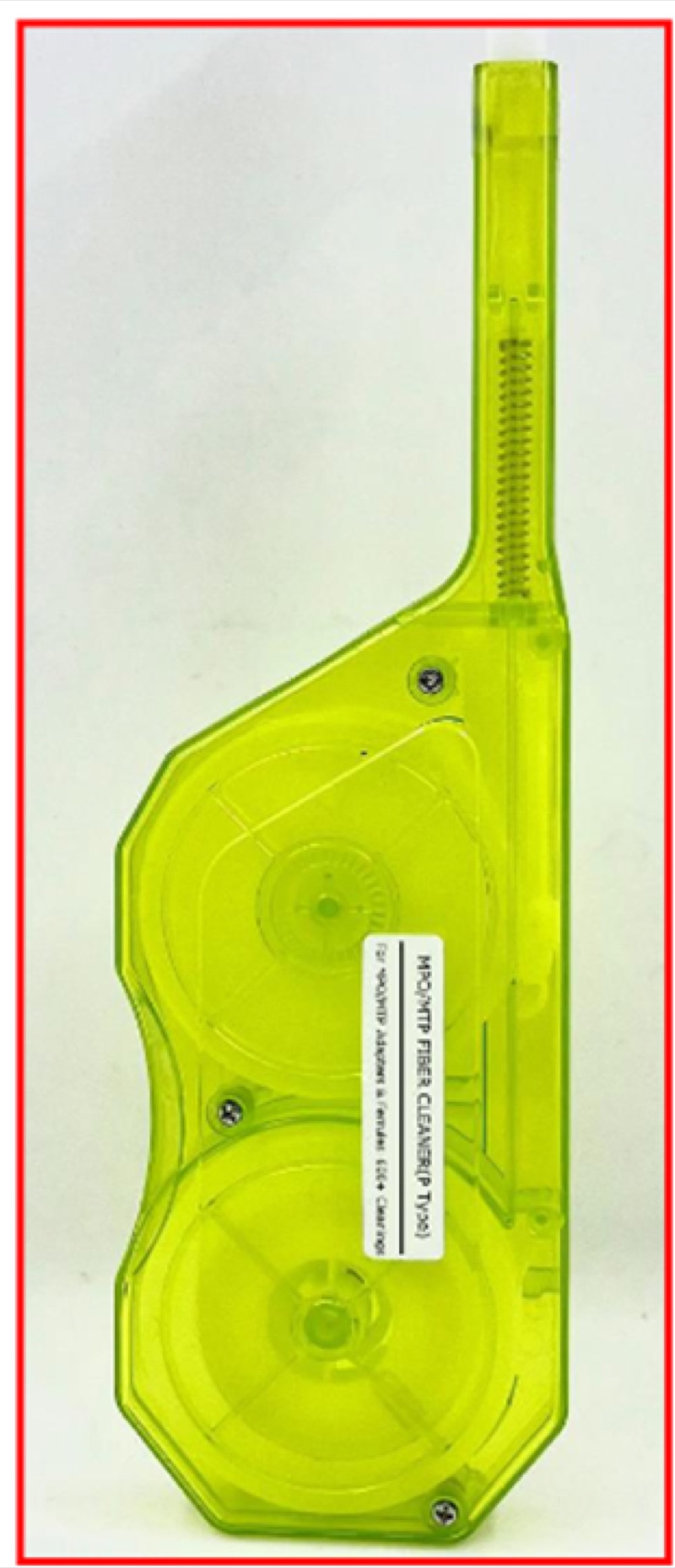
If any connector fails inspection, clean it with the appropriate cleaner and re-inspect. Common cleaning tools include the Opti Fiber Cleaner for LC and the MPO Push-Type Cleaner for MPO endfaces.
Step 2: Set Up the Test Source and Reference
Power on the OLTS source and meter. Allow the source to stabilize for the warm-up period specified by the manufacturer (typically 5 to 15 minutes for laser sources). Set the source wavelength to match the application: 850 nm for SR4 multimode, 1310 nm for DR1 and LR4 single-mode.
Connect the EF-compliant launch jumper between the source and the meter through a single coupler. Read the source power and store it as the reference (zero) value. This is the one-jumper reference method, which includes both terminating connectors of the link under test in the measured loss. Other reference methods (two-jumper, three-jumper) exist; use whichever is specified by the project.
For multimode testing, verify that the launch jumper is EF-compliant. A non-compliant launch can shift the measured loss by 0.5 dB or more, which is enough to fail a 100GBASE-SR4 channel that would otherwise pass.
Step 3: Measure End-to-End Insertion Loss
Connect the link under test between the source and meter. The reading on the meter is the channel insertion loss in dB.
For an MPO link, the OLTS may test all 12 fibers in a single sweep (modern test sets) or one fiber at a time using a fan-out. Either way, record the loss for each fiber.
Reverse the source and meter and repeat the measurement. The certified loss is the average of the two directions. TIA-568 requires bidirectional testing because connectors and splices can show direction-dependent losses, especially MPO connectors with mismatched ferrule alignment.
For LC duplex links, an Optical Power Meter LC handles the standard data center termination type.
Step 4: Verify Polarity
Polarity confirmation is critical for any MPO link. The OLTS measurement gives you loss but does not necessarily confirm that fiber position 1 at end A maps to fiber position 1 (Method A or C) or position 12 (Method B) at end B.
The simplest check is with a VFL Pen Type 5 km. Inject red laser light into one MPO fiber position at end A and visually confirm which position lights up at end B. Repeat for at least two non-adjacent positions to catch pair-swap errors.
For a Method B trunk feeding parallel-optic transceivers directly via MPO patch cords, expect fiber 1 at end A to light up at fiber 12 at end B, fiber 2 to fiber 11, and so on. For a Method A or Method C trunk, the expected mapping differs. See our MPO polarity methods guide for the full mapping table.
Step 5: Run OTDR Traces (Tier 2)
The OTDR maps the channel and identifies every event with its individual loss and reflectance. For 100G acceptance testing, run an OTDR trace on every fiber in both directions and archive the trace files.
OTDR Configuration
- Wavelength: 850 nm (and optionally 1300 nm) for OM4 multimode; 1310 nm and 1550 nm for OS2 single-mode.
- Pulse width: Short pulse (3 to 10 ns) for short data center links; longer pulse for inter-building runs. Shorter pulse means smaller dead zone and better event resolution.
- Range: Set to slightly more than the expected fiber length plus a launch and tail cord allowance.
- Averaging time: Longer averaging produces a cleaner trace. 30 to 60 seconds is typical for high-quality traces.
- End-of-fiber threshold: Configure so the OTDR correctly identifies the end of the link.
The Fiber Ranger OTDR handles typical data center link lengths and supports both multimode and single-mode wavelengths.
Reading the Trace
Each connector should appear as a small step (loss event) and possibly a reflection peak. Each fusion splice should appear as a step with no reflection. The fiber length should match the expected channel length within the OTDR's index of refraction tolerance. Look for unexpected events (macrobends appear as gradual slopes) and high-loss connectors (above the per-component allowance).
For more on reading OTDR traces, see our OTDR basics guide.
Step 6: Document and Archive
Generate a certification report for each fiber in the channel. The report must include:
- Identification: Building, room, panel, port, fiber number.
- Fiber type: OM4, OS2, etc.
- Length: From OTDR or measured.
- Polarity method: A, B, or C.
- Insertion loss: Bidirectional, averaged, at each test wavelength.
- OTDR trace: Raw .sor files for both directions, plus annotated reports.
- Pass/fail summary: Against the target IEEE application (e.g., 100GBASE-SR4).
- Equipment: Test set serial numbers, last calibration date.
- Technician: Name and date.
Most data center owners require the raw test files (typically .sor for OTDR, .flw or vendor-specific for OLTS) for archive and future re-analysis. Do not just deliver PDF reports; deliver the raw data too.
Pass/Fail Criteria
| 100G Variant | Fiber | Wavelength | Max Channel Loss | Per-Connector Allowance |
|---|---|---|---|---|
| 100GBASE-SR4 | OM4 | 850 nm | 1.9 dB | 0.50 dB max LC, 0.75 dB max MPO |
| 100GBASE-SR2 (PAM4) | OM4 | 850 nm | 1.9 dB | 0.50 dB max LC, 0.75 dB max MPO |
| 100GBASE-DR1 | OS2 | 1310 nm | 3.0 dB | 0.50 dB max LC |
| 100GBASE-FR1 | OS2 | 1310 nm | 4.0 dB | 0.50 dB max LC |
| 100GBASE-LR4 | OS2 | 1310 nm | 6.3 dB | 0.50 dB max LC |
The channel-level pass/fail is straightforward: total loss below the application budget. Per-event allowances apply to individual connectors and splices on the OTDR trace. A channel with one bad connector at 0.6 dB might still pass total loss if other connectors are very clean -- but the bad connector is a future failure waiting to happen.
Recommended Test Kit for 100G
OTDR
Handheld OTDR with multi-wavelength support and short dead zone for in-DC link testing.
Use: Fiber Ranger OTDR
VFL for Polarity
5 km visual fault locator for polarity verification and short-fiber troubleshooting.
Use: VFL Pen Type 5 km
Inspection
Microscope plus appropriate tips for LC and MPO endfaces.
Use: WiFi Fiber Microscope with LC/APC tips
The Bottom Line
Testing a 100G fiber link is a procedural exercise that depends on doing every step correctly: inspect, clean, reference, measure bidirectionally, verify polarity, capture OTDR traces, and document. The 1.9 dB budget for short-reach 100G leaves no margin for shortcuts. A channel that passes all these steps is one you can hand off to operations with confidence; a channel that skips any of them is a future trouble ticket.
For more depth on the certification standards, see data center fiber cable certification requirements. For the specific application loss budgets across 40G, 100G, and 400G, see 40G vs 100G vs 400G Ethernet fiber requirements. For OTDR trace interpretation, see OTDR basics.