The Quick Answer
Understanding Co-Location Cabling Topology
A co-location data center has a layered topology that determines who owns and manages each segment of fiber. Understanding the layers prevents surprises during installation and outages.
The Cabinet (Tenant Space)
The cabinet is leased space within the data hall. Tenant equipment (servers, switches, storage) lives here. The tenant is fully responsible for cabling inside the cabinet, including all patch cords from equipment to the demarcation patch panel.
The Demarcation Patch Panel
The demarc panel is the boundary between tenant and colo. It is mounted in the top or middle of the cabinet. The tenant side connects to equipment with patch cords like the SM LC/UPC Duplex Patch Cord for single-mode equipment. The colo side connects to the inter-cabinet trunk that runs to the meet-me room.
The Inter-Cabinet Run
Fiber from the demarc panel to the meet-me room. In most colos this is colo-owned and installed under a structured cabling agreement. The tenant pays per fiber pair or per circuit but does not touch the cable.
The Meet-Me Room (MMR)
A neutral interconnection space where the inter-cabinet trunk terminates on colo-managed panels. From here, the colo installs cross-connects to carrier panels, cloud provider panels, and other tenants based on tenant orders.
The Cross-Connect
A short patch cord (or longer dedicated run) in the MMR that bridges the tenant's MMR panel to the destination's MMR panel. This is the actual interconnection that the colo bills monthly.
Fiber Type Decisions
Single-Mode OS2: The Default
Single-mode OS2 is the universal default for colo cross-connects. It supports any rate (1G to 400G+) at any reasonable distance, works with both UPC and APC polish, and is what every carrier and cloud provider expects. The cost difference vs multimode at trunk scale is small. See single-mode vs multimode fiber for the full comparison.
Multimode OM4: Limited Use
Multimode is rare in colo cross-connects because the distance from the tenant cabinet to the MMR can exceed multimode reach for higher rates, and the colo wants flexibility to interconnect with anyone. Multimode is sometimes used for in-cabinet patching (server to top-of-rack switch) where transceiver cost matters and distance is bounded. The MM OM4 Simplex Jumper handles in-cabinet multimode patching.
UPC vs APC Polish
UPC (ultra physical contact) is standard for most data center applications. APC (angled physical contact) is required for any link with high back-reflection sensitivity: PON, DWDM, longer single-mode runs, or specific carrier handoffs. Many colos default to APC for cross-connects to be safe. Always confirm with the colo and the destination before ordering. See SC/APC vs UPC connectors for details.
Connector Selection Quick Reference
| Use Case | Fiber | Connector | Polish | Notes |
|---|---|---|---|---|
| Cross-connect to carrier (Layer 2/3) | OS2 | LC duplex | UPC or APC | Confirm with carrier |
| Cross-connect to cloud (AWS DX, Azure ER) | OS2 | LC duplex | UPC | 1G/10G/100G |
| Cross-connect to ISP (transit) | OS2 | LC duplex | UPC | 1G/10G/100G |
| Cross-connect for DWDM/wavelength | OS2 | LC duplex | APC | Required for low back-reflection |
| In-cabinet server to TOR switch | OM4 or OS2 | LC duplex | UPC | Match transceiver |
| In-cabinet TOR switch to demarc | OS2 | LC duplex | Match colo | Future-proofing |
Polarity Coordination with the Colo
Most colos use Method B polarity for MPO trunks and standard A-to-A polarity for LC duplex cross-connects. If your in-cabinet cabling uses a different scheme, the cross-connect will not work or will work intermittently.
For LC duplex cross-connects, the simplest rule is: use a standard A-to-B duplex jumper (which has the polarity flip built in) for every cross-connect. Both ends of the cross-connect should land on the colo's panels with the colo's expected pinout, and the duplex jumper handles the TX-to-RX pairing.
For MPO cross-connects (rare in classic colo, common in some hyperscale cabling-as-a-service offerings), confirm the polarity method with the colo and order all components to match. See MPO polarity methods A, B, and C explained for details.
Provisioning Strategy
Order More Strands Than You Need
Inter-cabinet runs from your cabinet to the MMR are expensive to install but cheap per strand once the conduit is in place. Order at least 12 strands (6 duplex pairs) for an initial cabinet, even if you only plan to light 2 strands at first. New cross-connects are far cheaper to provision against existing strands than against a new pull.
Pre-Provision MMR Panels
Many colos let you reserve MMR panel space in advance. Reserving a 12-fiber LC panel in the MMR ahead of need locks in the demarcation point and lets you order cross-connects against known fiber positions when needed.
Document Everything
Maintain a spreadsheet or CMDB of every fiber in your cabinet: position, fiber type, connector, polish, destination (carrier, peer, internal), and current circuit identifier. When something fails at 3 AM, this document is the difference between a 30-minute resolution and a 6-hour outage.
Testing Inside Your Cabinet
The colo certifies the inter-cabinet run. You are responsible for testing everything from your equipment to the demarc panel.
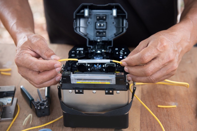
Endface Inspection
Inspect every patch cord before mating. The WiFi Fiber Microscope handles inspection. For LC patch cords specifically, the LC/APC Male Inspection Tip handles patch cord ends.
Power Measurement at the Demarc
Use an Optical Power Meter LC to measure receive power at the demarc panel after the colo has provisioned the cross-connect. Compare against the carrier or cloud provider's specified power range. If power is outside spec, the issue is on the colo side and they need to investigate.
Fiber Identification
An Optical Fiber Identifier confirms which fiber is live without disconnecting it -- essential when troubleshooting in a dense cabinet where labels may be ambiguous.
Cleaning
Clean every connector before mating. The Opti Fiber Cleaner handles standard LC cleaning. For long-form connector cleaning in tight cabinet spaces, the Fiber Lock Long Cleaner is useful.
Common Tenant Cabling Pitfalls
- Mismatched polish (UPC vs APC). Plugging a UPC connector into an APC bulkhead causes a large reflection and damages both endfaces. Always confirm polish with the colo and the destination.
- Under-provisioning strands. Ordering 2 strands today and finding out next quarter that you need 8 means a new fiber pull at significantly higher cost than ordering 12 up front.
- Skipping demarc documentation. Without clear demarcation documentation, every troubleshooting call becomes a finger-pointing exercise between tenant and colo.
- Using the wrong patch cord length. Long jumpers coiled in the cabinet create congestion and stress fibers. Order the right length.
- Forgetting to label both ends. Every patch cord should have durable labels at both ends with cabinet, panel, and port references.
- Not archiving colo certification. When the carrier reports loss issues months later, the original certification is the baseline you compare against. Get the .sor and .flw files at handoff.
Real-World Install Scenarios
Three patterns that come up routinely on colo deployments and how to plan for them at the order stage rather than discovering them at cutover.
Scenario 1: Carrier diversity with two MMR paths
A tenant in financial services needs two physically diverse paths from the cabinet to two different carrier MMRs (meet-me rooms) in the same building. The colo has primary and secondary MMRs on different floors with separate riser paths. Order Form A: 4-strand OS2 LC/UPC from cabinet to MMR-1. Order Form B: 4-strand OS2 LC/UPC from cabinet to MMR-2. Document both as-built diagrams in a single tenant binder. When the carrier eventually announces a maintenance window, the tenant can verify true diversity from the colo's records rather than from the carrier's claim.
Scenario 2: Cloud onramp added to an existing tenant cabinet
A tenant lands AWS Direct Connect at 10G in their cabinet. Six months later they add Azure ExpressRoute and Google Cloud Interconnect. The original cross-connect order spec'd 12 strands of OS2 to the colo's cloud onramp panel even though only 2 were used at install. Adding the second and third cloud connections requires only a colo cross-connect ticket and a new patch cord at the tenant cabinet -- no new fiber pull, no after-hours work. Total time from cloud provider approval to live circuit: roughly four business days (gated by colo paperwork, not physical work).
Scenario 3: Polish-mismatch RMA caught at first power reading
A tenant orders LC/UPC patch cords for what the colo provisioned as LC/APC bulkheads. The first power reading shows 8 dB of unexplained loss. Endface inspection reveals the polish mismatch and visible damage to the bulkhead from the UPC ferrule. The colo replaces the damaged bulkhead under SLA, and the tenant re-orders APC patch cords. Lesson: confirm the bulkhead polish in writing on the colo cross-connect ticket before ordering patch cords, and inspect every endface on first mate so damage is caught before it propagates.
Scenario 4: Multi-region replication circuit with metro DWDM handoff
A tenant signs up for a metro 100G DWDM service from a regional carrier to replicate data between two colos in different cities. The carrier hands off at LC/UPC on a 100G-LR4 wavelength in each city. The tenant's responsibility starts at the demarc panel; the carrier's responsibility ends there. The tenant orders pre-tested LC/UPC patch cords in matched pairs and labels each with a unique circuit ID that matches the carrier's order paperwork. When the circuit eventually flaps months later, the tenant can hand the carrier a single-line trouble ticket with the circuit ID, the demarc port, and the receive power reading — the carrier locates and resolves the upstream issue without requiring tenant-side site access.
Demarc Documentation Standards
The single highest-leverage document in any colo cabling deployment is the demarc inventory. It defines the boundary between tenant and provider responsibility for every circuit and survives organizational changes on both sides.
- One row per circuit. Each cross-connect, transit handoff, and cloud onramp is a single row. Bidirectional circuits are still one row with both endpoints recorded.
- Endpoints in colo coordinates. Cabinet number, panel position, port number on both ends — never just a description like "AWS port" or "primary uplink."
- Polish, polarity, fiber type per endpoint. LC/APC OS2 on the carrier side does not imply LC/APC OS2 on the tenant side; both must be recorded explicitly.
- Original installation date and provider work order number. Lets you trace back to the colo's records when bulkhead labels become illegible after a few years.
- Power reading at acceptance and at last quarterly check. Trending power across quarters catches connector degradation before it becomes an outage.
- Customer-facing label and operator-facing label. Sometimes different; e.g., your internal name "DR-replication-east" and the carrier's circuit ID "100G-METRO-49823."
Operators that maintain a clean demarc inventory respond to incidents in minutes; operators without one spend hours rebuilding history before they can begin troubleshooting. The cost of maintaining the document is a few minutes per circuit at install — the savings are measured in MTTR.
Quarterly Audit Checklist for Tenant Cabinets
Tenant cabinets in colos drift from their as-built state more quickly than internal data centers because changes happen across organizational boundaries (carrier, colo, tenant). A simple quarterly audit catches drift before it becomes operationally painful.
- Compare physical labels to the demarc inventory. Walk the cabinet, read every label, mark any discrepancies for follow-up.
- Verify polish and polarity at every patch point. Visual inspection plus a power reading on a known reference confirms nothing has been swapped without notice.
- Re-take the patch panel photographs. Compare to the previous quarter's photos for added or removed cords.
- Trend power readings against the baseline. Loss creep of more than 0.5 dB on any circuit warrants endface inspection and possible patch cord replacement.
- Confirm spare patch cord inventory in the cabinet. Every cabinet should hold at least 5 LC/APC and 5 LC/UPC patch cords in dust-protected sealed bags for emergency use.
Coordination Patterns That Avoid Cross-Connect Delays
Cross-connect provisioning timing is the single largest source of frustration in colo deployments. A few coordination patterns reduce this dramatically.
- Pre-stage the cross-connect ticket before the carrier ticket. The colo cross-connect almost always takes longer than the carrier circuit; opening the colo ticket first prevents the colo from being the long pole.
- Provide complete endpoint information in writing. Cabinet, panel, port, polish, polarity, fiber type. Incomplete tickets get bounced and reset the queue.
- Coordinate carrier and colo work windows. The carrier turns up the circuit on a planned date; the colo's cross-connect must be live by that date. Work backward from the carrier date.
- Confirm power and continuity at first opportunity. Some colos charge for "smart hands" support to verify a circuit; pay it. The cost of detecting a wiring problem during a maintenance window is far lower than the cost during a production cutover.
- Maintain a relationship with a named contact at each colo. Generic ticket queues are slower than a named technician who knows your account. Build the relationship before you need it.
Common Tenant Questions
Who pays for the cross-connect inside the colo?
The tenant pays the colo a one-time install fee plus a monthly recurring charge per cross-connect. Carriers and cloud providers typically bill their portion separately. Confirm both fees in writing before ordering.
Can we install our own fiber between cabinets?
Most colos prohibit tenant-installed fiber outside the cabinet for safety and operational reasons. The colo retains exclusive control of the cabling between cabinets and the meet-me room. Tenant fiber work is generally limited to inside the leased cabinet.
How long does a typical cross-connect provisioning take?
Standard cross-connects within the same data center take 2 to 5 business days from ticket submission to live circuit. Cross-building or cross-suite cross-connects can take longer. Carrier and cloud onramps depend on the upstream provider's queue, often 5 to 10 business days.
Should we order single-mode or multimode for a colo cross-connect?
Default to single-mode (OS2) for colo cross-connects. Distances inside a colo can exceed multimode reach for higher speeds, and single-mode futures-proofs the path against bandwidth growth. Multimode is only appropriate for very short runs (under 100 m) where the optic vendor specifically supports it.
What documentation should we keep on every cross-connect?
The colo cross-connect ticket number, the carrier's circuit ID (if applicable), the demarc cabinet and port, the polish and polarity, the acceptance power readings, and the install date. Store as a single CSV per colo location, not as scattered tickets in a generic ticketing system.
Can we run our own patch cords across the cage to neighboring cabinets?
Inside a single tenant's contiguous cage, yes. Across the floor between non-adjacent cages, no — that requires a colo-managed cross-connect through the meet-me room. Confirm with your colo's tariff; rules vary by provider.
How should we handle a colo cabinet move-out?
Inventory every cross-connect, every demarc port, and every patch cord before move-out begins. Coordinate disconnect order with carriers and cloud providers to avoid premature billing termination. Recover all tenant-owned patch cords from the cabinet for re-use; the colo will keep tenant-owned bulkheads as part of the cabinet hardware.
The Bottom Line
Co-location fiber cabling is mostly about coordination and provisioning, not technology. The fiber type and connectors are well-known defaults (OS2 with LC); the hard part is ordering enough strands, documenting demarcation clearly, coordinating polish and polarity with the colo, and maintaining the cable plant documentation that lets you provision new connectivity quickly. Tenants who treat colo cabling as an operational discipline get fast cross-connect provisioning; those who treat it as an afterthought spend hours troubleshooting at every change.
For the broader data center cabling architecture, see our structured fiber cabling for data centers guide. For testing the fiber inside your cabinet, see how to test a 100G fiber link. For polarity coordination, see MPO polarity methods A, B, and C explained.