Why Inspection Comes First
The single-mode core is 9 micrometers in diameter. The IEC pass/fail threshold for a defect in Zone B (the cladding zone) is 3 micrometers. Both numbers are well below the resolution of the human eye, which tops out around 50 to 100 micrometers under good lighting. Without a microscope, you cannot see the contamination that determines whether a fiber link will pass acceptance testing. You are working blind.
A video inspection scope provides 200x to 400x magnification on a digital screen, which makes those tiny defects immediately visible. More importantly, a scope with auto pass/fail applies the IEC 61300-3-35 criteria objectively, so two technicians grading the same image reach the same verdict every time.
Choosing the Right Inspection Scope
Not all inspection scopes are equal. The three things that matter for field work are magnification, image stability, and connectivity.
Magnification
200x is the minimum useful magnification for IEC-grade inspection. 400x is better and is the standard for auto pass/fail systems. Optical-only scopes (no display) typically provide 200x but offer no way to capture the image for documentation, so they are increasingly rare in professional work.
Display
WiFi and USB scopes stream the image to a phone, tablet, or laptop, which gives a large bright screen, easy image capture, and the ability to share results with the customer in real time. Standalone scopes with an integrated screen are simpler but limit screen size and capture options.
Auto Pass/Fail
Auto pass/fail scopes run the IEC 61300-3-35 algorithm in firmware and return a clear PASS or FAIL plus a defect count per zone. The QBL WiFi/USB Fiber Inspection Microscope ($1,249.99) includes auto pass/fail and works with iOS, Android, Windows, and Mac. This is the level of capability you need for professional installation work where the customer expects documented inspection results.
Choosing the Right Inspection Tip
The inspection tip is the mechanical adapter that mates the scope optics with the connector you are inspecting. The tip determines how the scope aligns with the ferrule, which controls whether you get a centered, in-focus image or a tilted one that produces false fails.
Male vs Female Tips
A male tip is shaped to fit into a bulkhead-mounted adapter, like the back side of a patch panel where the technician needs to inspect the cable that has already been installed and terminated into the rear of the panel. A female tip is shaped to receive a patch-cord connector from the front of the panel, like inspecting a jumper before plugging it into a port. You need both for a complete inspect-before-connect workflow.
| Connector Type | Tip You Need | Use Case | Where Used |
|---|---|---|---|
| LC/APC (bulkhead) | LC/APC Male Tip | Inspect rear of installed bulkhead | FTTH, data center patch panels |
| LC/APC (patch cord) | LC/APC Female Tip | Inspect jumper before mating | FTTH drop, OLT pigtails |
| SC/UPC, SC/APC | 2.5mm Universal Tip (often included) | Inspect both bulkhead and patch cord | Trunk and distribution |
| MPO/MTP | MPO Tip (specialty) | Inspect ribbon ferrule array | Data center high-density |
Why the Right Tip Matters
An incorrectly mated tip produces a tilted image. The IEC zone overlay assumes the ferrule is perfectly centered and perpendicular. A tilted image shifts the apparent zone boundaries, putting Zone D contamination inside Zone A on the image and triggering a false fail. Always use the tip designed for the connector you are inspecting.
Inspection Procedure: Step by Step
Step 1: Power Up and Pair
Turn the scope on and connect it to your phone, tablet, or laptop via WiFi or USB. Confirm a live video feed appears in the viewing app. Most professional scopes are ready in under 15 seconds.
Step 2: Select the Correct Profile
In the viewing app, select the fiber type and connector profile (single-mode UPC, single-mode APC, multimode 50um, multimode 62.5um). The profile sets which IEC template the auto pass/fail uses. Selecting the wrong profile guarantees inaccurate results.
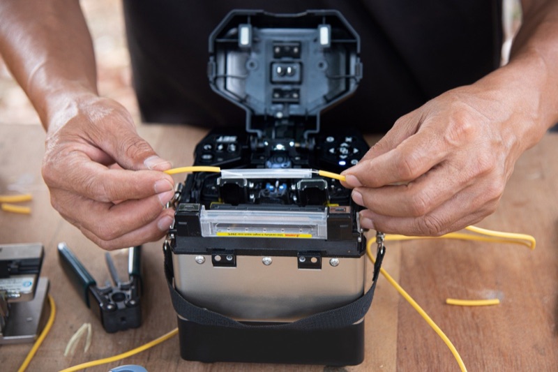
Step 3: Attach the Inspection Tip
Thread the correct tip onto the scope nose. Hand-tight only -- do not torque the tip down. Some tips have a keyway that aligns with the scope; align before threading.
Step 4: Mate the Tip to the Connector
For a patch cord, insert the connector into the female tip until it seats. For a bulkhead, push the male tip into the adapter port until it bottoms out. The image should appear immediately. If you see only black or blur, the tip is not seated properly.
Step 5: Focus
Adjust the focus ring on the scope until the end-face is sharp. Defects, particles, and scratches should appear crisp and clearly defined. A blurred image produces unreliable pass/fail results because the algorithm cannot accurately size defects.
Step 6: Capture and Grade
Press the capture button. The scope freezes the image, applies the four-zone overlay, counts defects in each zone, and returns PASS or FAIL with a per-zone defect count. Save the image with a descriptive filename (cabinet ID, port number, date).
Step 7: Clean if Needed, Re-Inspect
If the result is FAIL, clean the connector with the appropriate one-click cleaner and re-inspect. Repeat until PASS. If repeated cleaning does not produce PASS, the connector likely has embedded scratches or pits and must be replaced or re-polished.
Common Inspection Mistakes
- Wrong tip: Using a male tip on a patch cord (or vice versa) produces a tilted off-center image. Always match tip to use case.
- Wrong fiber profile: Selecting multimode template when inspecting single-mode produces false passes because the multimode Zone A is more permissive.
- Image not focused: Auto pass/fail relies on edge detection. A blurred image hides defects from the algorithm.
- Off-center capture: If the ferrule is not centered in the field of view, the zone overlay misaligns. Re-seat the tip and recapture.
- Skipping documentation: Save every inspection image with traceable filename. The image is your warranty defense and your customer's acceptance proof.
- Inspecting only one side: Bulkhead and patch cord both need inspection. Skipping one side defeats the purpose of inspect-before-connect.
Documenting Inspection Results
Inspection results are not just for the technician's confidence. They are increasingly required deliverables on commercial fiber projects.
What to Capture
For each connector: the captured image, the PASS/FAIL result, the connector ID (cabinet number, port number, fiber number), and the date. Many enterprise customers also require the technician name, the scope serial number, and the calibration date of the scope.
Format and Storage
PNG or JPG with the IEC overlay baked into the image. Filenames should be machine-sortable: 2026-04-15_DC1-RACK12-PANEL3-PORT24_LC-APC_PASS.png. Store in a project folder organized by site and date. Most modern scopes export directly to cloud storage, which simplifies handoff to the customer.
What to Do with Failures
Save the failure images too. They document the work you performed (clean attempts, escalation to wet clean, ultimately replacing the connector). When a customer questions a connector six months later, the inspection record proves the connector passed at installation.
What to Carry in the Truck
A complete fiber inspection setup covers every connector type you might encounter and every cleaning escalation path. Here is the field-proven kit:
Pre-Built Kit
The Fiber Cleaning Kit ($99.99) covers cleaning supplies. Add the inspection scope separately for a complete inspect-and-clean rig.
The Bottom Line
Inspection is the verification step that turns fiber installation from guesswork into engineering. A good scope with the right tip and the right profile gives you an objective PASS or FAIL on every connector you mate, and the captured image is the proof you delivered work to spec.
Carry a scope. Use it on every connector. Save the images. The 10 seconds per connector you spend on inspection prevents the multi-hour troubleshooting calls that cost real money. For a deeper look at the zone overlay system, see Fiber End-Face Zones Explained. For the standard itself, see IEC 61300-3-35. For the cleaning protocol that works hand in hand with inspection, see Fiber Optic Cleaning Best Practices.