Why Splice Tray Organization Matters
The splice itself is permanent. The tray that holds it is the long-term housing — and it gets opened and worked in many times over the life of the fiber plant. Every future repair, every future cable add, every fault investigation involves pulling the tray, finding the right fiber, and working with it without disturbing the others.
A well-organized tray makes that future work fast and safe. A poorly organized tray turns a 10-minute repair into a 3-hour ordeal where you risk breaking adjacent fibers just to access the one you need. The discipline is up-front, but the payoff is years of easy maintenance.
The Five Rules Every Tech Should Follow
Bend Radius: The Number One Rule
Optical fiber tolerates being bent, but only to a point. Bending a fiber tighter than its minimum bend radius causes signal loss (macrobend loss, often wavelength-dependent and worse at 1550nm than 1310nm) and over time can cause fiber fatigue and breakage.
Minimum Bend Radius Numbers
- Standard single-mode (G.652): 1.5 inches (38mm) long-term, 1 inch (25mm) short-term during pulling.
- Bend-insensitive single-mode (G.657.A2): 0.6 inches (15mm) long-term.
- Ultra bend-insensitive (G.657.B3): 0.2 inches (5mm) long-term.
- 900-micron tight-buffer fiber: 1.5 inches (38mm) long-term — same as 250-micron because the buffer adds stiffness, not protection from bending.
- Multimode 50/125 OM3/OM4: 1.0 inches (25mm) long-term.
How Trays Enforce Bend Radius
Modern splice trays have molded plastic loop guides — circular or oval channels that fibers route around. The guides are sized to enforce minimum bend radius. Use them. The temptation to take shortcut routing across the middle of the tray to save loop length will produce a tight bend at the edge of the splice holder where the fiber transitions from straight to coiled. That tight bend is a future loss point.
Free: Splice Tray Layout & Labeling Checklist
A one-page printable card for the closure: minimum bend-radius numbers by fiber type, the 12-color TIA-598 routing sequence, the slack rule, and a fill-in splice-schedule template for the tray cover. Sized to laminate and keep in your splice kit. Drop your email and we'll send it over.
No spam. We'll send the resource and the occasional fiber-splicing tip. Unsubscribe anytime.
Cable Entry and Strain Relief
Cables enter the splice closure or fiber distribution panel through grommeted ports. Each cable gets a strain relief — a clamp or boot that holds the cable jacket so any force on the cable is borne by the jacket, not the fragile bare fibers inside.
At the strain relief point, label the cable. The label should identify both ends of the cable and ideally the cable ID from the as-built drawings. Use heat-shrink labels or weatherproof printable labels — not paper tape that falls off in 6 months.
Inside the closure, route the buffer tubes from the entry port to the splice tray. Maintain bend radius on the buffer tubes too. Leave a service loop of 0.5-1 meter of buffer tube so future re-entries do not require pulling more cable.
Tray Layout: A Step-by-Step Approach
Step 1: Identify the Tray Type
Single-fiber splice trays have a row of splice holders along one or two sides with looping channels around the perimeter. Mass-fusion ribbon trays have wider holders for ribbon protection sleeves. Confirm the tray matches your splice type before starting.
Step 2: Plan the Routing
Decide which side each cable will enter. Typically Cable A enters one side, Cable B enters the opposite side, splices live in the holders along the bottom or center. The tray cover should show this routing on a printed diagram.
Step 3: Strip and Prep
Strip the buffer tube to expose individual fibers. Maintain the color-coded twist of the fiber bundle. Strip just enough to reach the splice holders with the planned slack — typically 25-30cm of bare fiber per side.
Step 4: Route to Splice Holders
Route fibers in color order. Blue (position 1) goes to splice holder 1. Orange (position 2) goes to holder 2. Green to 3. And so on through the standard 12-color sequence (blue, orange, green, brown, slate, white, red, black, yellow, violet, rose, aqua). Both cables route their position-1 fibers to the same holder so the splice connects color-to-color.
Step 5: Splice, Protect, and Mount
For each fiber pair, fusion splice (see step-by-step splice guide), slide the heat-shrink protection sleeve over the splice point, heat to set, and mount the protected splice in the holder slot. Work fiber 1 to fiber 12 in order so adjacent splices in the tray correspond to adjacent fibers in the cable.
Step 6: Coil the Slack
After all splices are seated, coil the remaining slack of each fiber around the tray's loop guide. The coils should sit flat, follow the guide, and not cross other fibers. If the slack is too long, take a second loop. Never trim slack to make it fit — leave the spare for future repairs.
Step 7: Document and Cover
Write the splice schedule on the tray cover or attach a printed map: which cable, which fiber color, which splice position, what the destination is. Date the tray. Initial it. Close the cover and seal the closure.
Tray Capacity Reference
| Tray Type | Splice Sleeve | Capacity | Best Use |
|---|---|---|---|
| Standard single-fiber tray | 40mm heat-shrink | 12 splices | FTTH drops, small distribution |
| High-density single-fiber tray | 25mm micro-sleeve | 24 splices | Compact closures, density-constrained |
| Large single-fiber tray | 40mm heat-shrink | 24-48 splices | Mid-size distribution closures |
| Ribbon mass-fusion tray | Ribbon sleeve | 4-8 ribbons (48-96 fibers) | Backbone, data center, CO |
| Mixed splice/patch tray | Variable | 12 splices + 12 connector ports | FDP with splice and pigtail |
Always pick a tray with 25-50% headroom over your splice count. A fully packed tray is miserable to work in.
Tray Documentation
The tray cover (or a label adjacent to it) should always carry:
- Cable IDs for both sides of the splice — entering cable and exiting cable, matching as-built drawings.
- Splice schedule — table mapping fiber color to splice position to destination port or cable.
- Date of installation — when the tray was originally spliced.
- Tech initials — who did the work, for accountability and follow-up questions.
- Date of last entry — every time the tray is opened, log the date and reason.
This information goes onto a sticker, a laminated card, or printed directly into the closure. Over the life of the fiber plant the tray will outlive multiple technicians and the documentation is what makes future work possible.
For broader documentation discipline, see our FTTH as-built documentation guide.
Common Tray Organization Mistakes
- Crossing fibers. Fiber over fiber creates pressure points and makes future access impossible without disturbing neighbors. Route fibers in parallel always.
- Tight bends at the splice holder. Where the bare fiber emerges from the splice holder and starts its loop, the bend transition can sneak below minimum radius. Watch this point.
- Not enough slack. Cutting the slack short means future repairs require pulling cable jacket — a major operation. Always leave at least 30cm of working slack per fiber.
- Out-of-order routing. Skipping color order ("I'll just put blue here because it's closer") destroys the ability to predict fiber location. Always work in color order.
- Mixed sleeve sizes. Mixing 40mm and 60mm sleeves in the same tray means some splices stick up higher than others and the tray cover may not close. Use one sleeve size per tray.
- Unlabeled trays. A tray without documentation is a tray that future techs will treat as a black box. Label every tray.
- Overpacked trays. Filling all 12 holders in a 12-position tray leaves no room to work if you need to re-splice. Plan for 25-50% headroom.
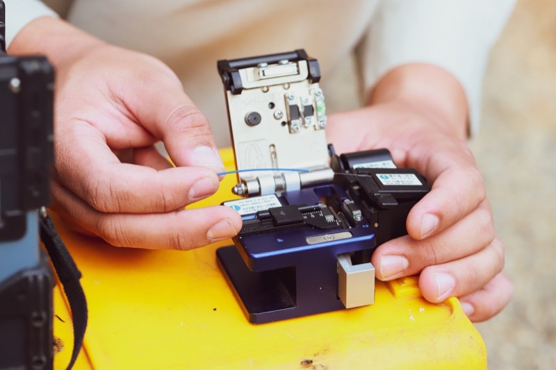
Tools for Splice Tray Work
Fusion Splicer
The QBL Fusion Splicer for single-fiber splices in distribution and FDP trays.
Fiber Splicing Kit
Strippers, alcohol, wipes, and protection sleeves needed for tray work.
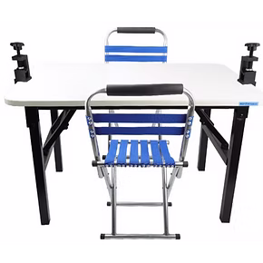
Splicing Table with Accessories
Stable working surface for tray-out splicing with built-in tray rest.
Fiber Identifier
Identify which fiber in a tray carries traffic before disturbing neighbors during repair.
VFL Pen 5km
Visual fault locator for tracing which port a fiber lands on inside a populated tray.
LC Connector Cleaner
Clean LC connectors before mating into adapter panels in mixed splice/patch trays.
Frequently Asked Questions
What is the minimum bend radius for splice tray fiber?
1.5 inches (38mm) for standard single-mode 250-micron and 900-micron tight-buffer fiber. 0.6 inches (15mm) for bend-insensitive G.657.A2 fiber. Use the tray's molded loop guides — they are designed to enforce these radii.
How much slack should I leave?
30-50cm of fiber slack per side, organized into one or two flat coils inside the tray. Enough to pull a fiber out and re-splice without restripping the cable jacket.
How many splices fit in a tray?
Standard single-fiber trays hold 12 splices with 40mm sleeves or 24 with 25mm micro-sleeves. Ribbon mass-fusion trays hold 4-8 ribbons (48-96 fibers). Pick a tray with 25-50% headroom over your splice count.
Can splices and patches share a tray?
Generally no. Use trays designed for the application. Mixed splice/patch trays exist for FDP applications where pigtails are spliced to incoming fibers, but they have dedicated splice and connector sections.
How do I label fiber in a tray?
Cable labels at strain reliefs, color-order routing inside the tray (TIA-598), and a splice schedule on the tray cover with cable IDs, fiber positions, dates, and tech initials.
Ready to build a splice tray the next tech will thank you for?
Tell us the closure — FTTH drop, distribution FDP, or ribbon backbone — and a fiber specialist will spec the fusion splicer, splice sleeves, and tray-out splicing kit that match your fiber count and bend-radius needs. No upsell, just the right gear.
“Spec'd a full FTTH splice kit in one call — splicer, sleeves, and tray-out table shipped next day.” — Field crew lead, regional ISP
Splice Closure and Tray Equipment
Fusion splicers, splicing kits, splicing tables, and inspection tools for clean, serviceable splice tray work.